Ice storage box structure

A box structure and box shell technology, applied in ice making, ice making, ice storage/distribution, etc., can solve the problems of not being able to change the volume of the storage cavity, accelerate the melting speed of ice cubes, and shorten the storage time of ice cubes, etc., to achieve Well-conceived, flat, easy-to-achieve effects

Inactive Publication Date: 2009-02-11
青岛澳润商用设备有限公司
View PDF10 Cites 0 Cited by
  • Summary
  • Abstract
  • Description
  • Claims
  • Application Information

AI Technical Summary

Problems solved by technology

Since the factory-set volume of the storage chamber remains unchanged, and there is no auxiliary structure in the storage chamber to change its volume space in the prior art, the user cannot change the volume of the storage chamber by himself, and then use it to change the ice storage capacity to better meet actual needs
This type of refrigerator has been used for a long time without any change
Moreover, the ice machines in the prior art adopt electrical automatic control to control the ice-making process, and the ice cubes in the storage chamber of the storage bin are often full or not as the control conditions for different operating states. The technical characteristics of the above-mentioned storage chamber determine the The user usually only needs much less than the factory-set ice storage volume, but the amount of ice cubes produced is always greater than the actual demand, which will inevitably cause unnecessary waste of energy and raw materials. The user cannot change this situation and can only helplessly. bear
In addition, the storage cavity of this type of storage body is very prone to the phenomenon that the ice cubes stored in the lower part are immersed in melting water, which will accelerate the melting speed of the ice cubes and shorten the storage time of the ice cubes

Method used


Image

  • Ice storage box structure
  • Ice storage box structure
  • Ice storage box structure

Examples


Embodiment Construction

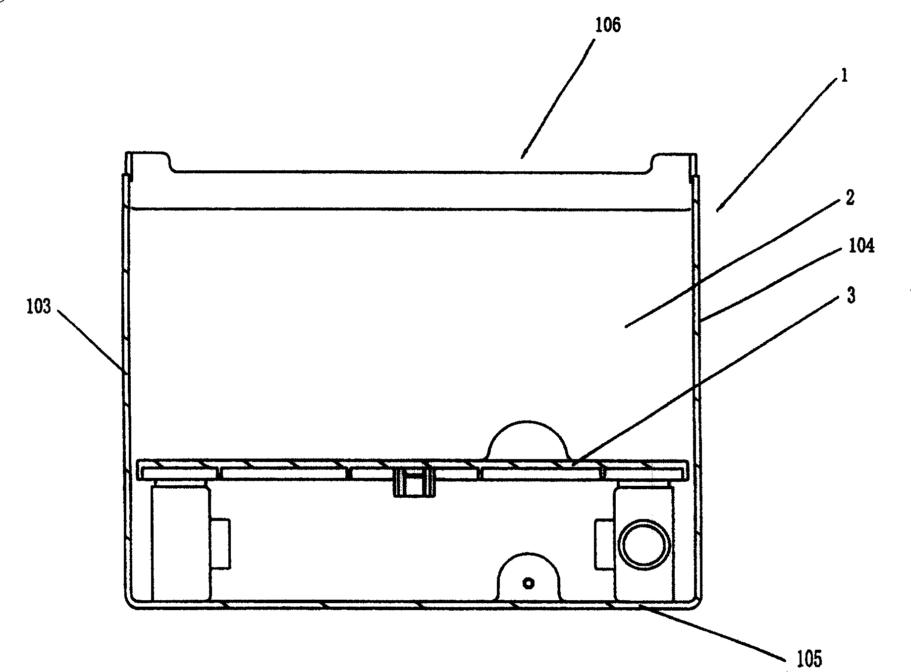
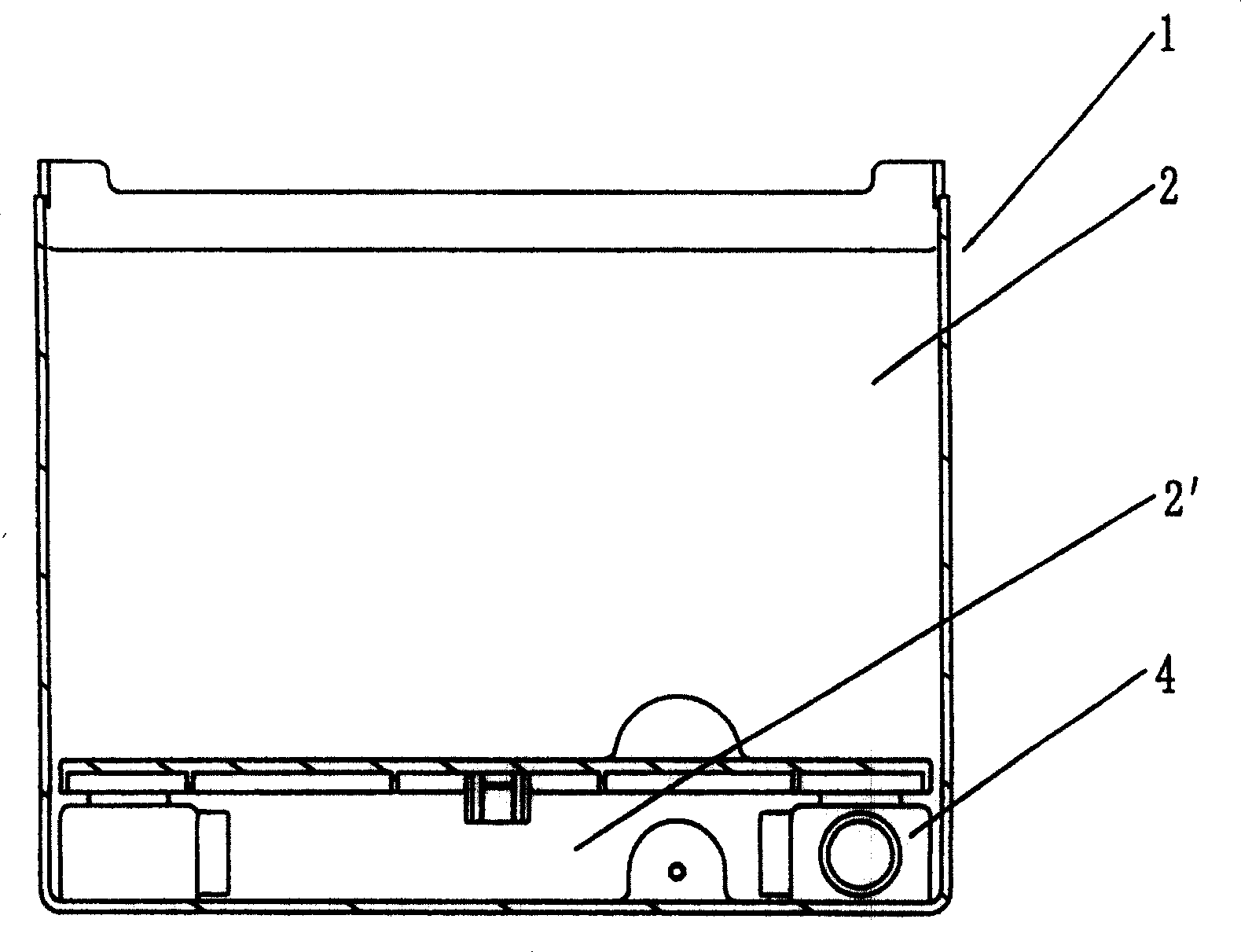
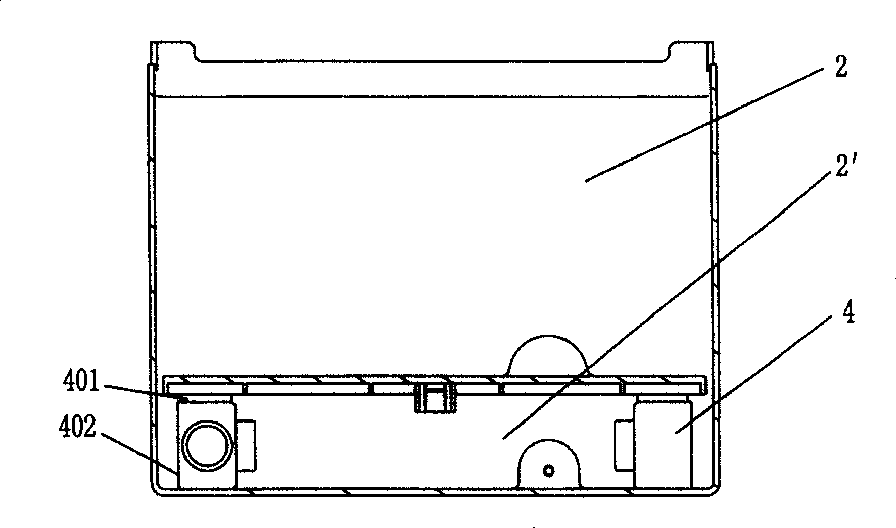
[0023] see figure 1 , Figure 4 with Figure 5 , a storage body structure, including a box shell 1 and a storage chamber surrounded by the box shell, the box shell 1 has a front side wall 101, a rear side wall 102, a left side wall 103, a right side wall 104 and a bottom side wall 105, the top of which is an opening 106. A transverse movable partition 3 is arranged in the storage chamber, and the movable partition 3 divides the storage chamber into an upper storage compartment 2 and a lower storage compartment 2 ', and the upper storage compartment 2 communicates with the lower storage compartment 2 ', that is, from the upper storage compartment 2 The water body flows down into the lower storage sub-chamber 2', and the connection can take the following specific technical methods, such as adopting a grid or a grid-like movable partition, and the water from above is guided downward through the holes on the partition; The partition can guide the flow downward through the gap l...


PUM


Abstract

The invention discloses an ice storage structure which consists of a storing cavity formed by the shell and the shell infold. There are front, back, left, right and bottom walls on the shell. The top of the shell is an open port. There is a transverse sliding baffle plate on above storing cavity alterable of different height in the cavity and dividing the cavity into upper and lower sub cavities. The clearance between the two sub cavities is reserved by the channel on the baffle plate or between the baffle plate and the side walls or communicating with other suitable ports. It acquires the features that the upper ice storage room is adjustable so to effectively separates the ice block and the water lengthening the storing period.

Description

technical field [0001] The invention relates to an ice maker, in particular to a storage body used in an ice storage room of the ice maker. Background technique [0002] In the prior art, the ice storage box used in the ice storage room of the ice machine is also called the ice storage box. This type of storage box includes a box shell and a storage cavity surrounded by the box shell. The box shell has front, rear, left, and right sides. And the bottom side wall, the top of which is an open mouth. The ice cubes made by the ice machine from the ice mold are received from the opening and temporarily stored in the storage chamber. Since the factory-set volume of the storage chamber remains unchanged, and there is no auxiliary structure in the storage chamber to change its volume space in the prior art, the user cannot change the volume of the storage chamber by himself, and then use it to change the ice storage capacity to better meet The purpose of its own actual needs. Thi...

Claims


Application Information

Patent Timeline
Patent Type & Authority Patents(China)
IPC IPC(8): F25C5/16F25C1/24
Inventor 张进富张明在冯永章
Owner 青岛澳润商用设备有限公司
Why Eureka
Try Eureka