Liquid crystal display panel and method for producing the same

A liquid crystal display and display area technology, applied in nonlinear optics, instruments, optics, etc., can solve the problem that the sealant 32c cannot be fully cured

Active Publication Date: 2009-01-28
SHARP KK
View PDF8 Cites 0 Cited by
  • Summary
  • Abstract
  • Description
  • Claims
  • Application Information

AI Technical Summary

Problems solved by technology

In this case, the sealant 32c present at the portion overlapping with the light-shielding layer 22 cannot be sufficiently cured.

Method used


Image

  • Liquid crystal display panel and method for producing the same
  • Liquid crystal display panel and method for producing the same
  • Liquid crystal display panel and method for producing the same

Examples


Embodiment Construction

[0090] A liquid crystal display panel and a method of producing the liquid crystal display panel according to embodiments of the present invention will be described below with reference to the accompanying drawings.

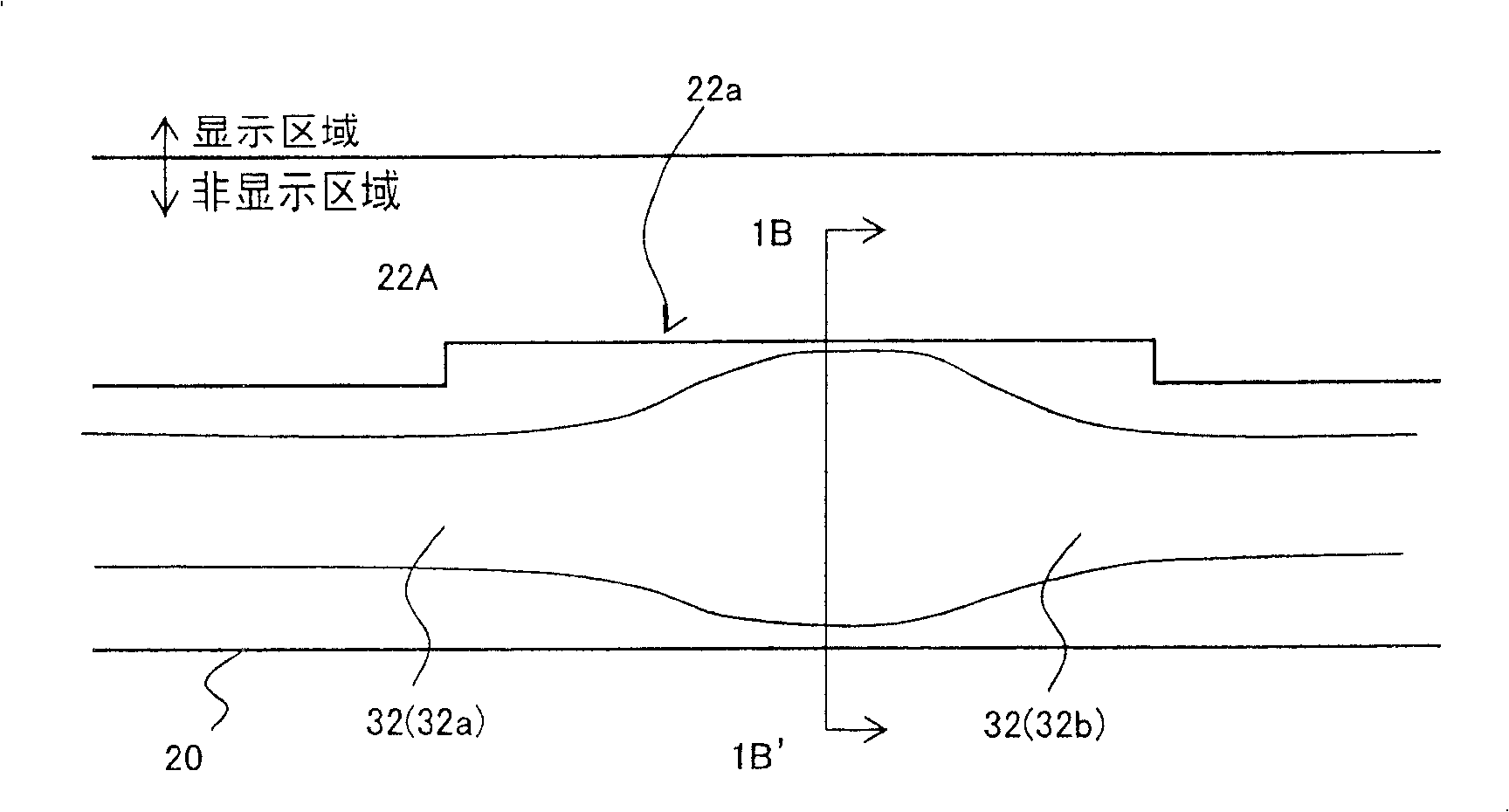
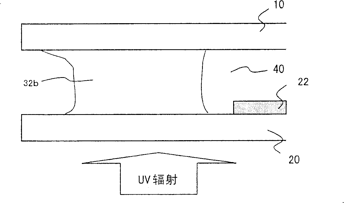
[0091] Such as Figure 1A and 1B As shown in , the liquid crystal display panel according to the embodiment of the present invention includes: a TFT substrate 10, a color filter substrate 20, a liquid crystal layer 40 disposed between the TFT substrate 10 and the color filter substrate 20, and surrounding liquid crystal layer 40 The sealing part 32 . The liquid crystal display panel has a display area and a non-display area surrounding the display portion. The color filter substrate 20 has a first light-shielding layer 22A provided in the non-display area at the end closer to the display area. The first light-shielding layer 22A has a concave portion (light-transmitting portion) 22a provided near the outer edge. The width of the sealing portion 32 is allowed ...


PUM

PropertyMeasurementUnit
depthaaaaaaaaaa
lengthaaaaaaaaaa
particle sizeaaaaaaaaaa

Abstract

The method of the present invetion includes the steps of: (A) providing a first substrate, and a second substrate, wherein the first substrate includes a first light shielding layer provided within a non-display region, the first light shielding layer including a light-transmitting portion provided near an outer boundary of the first light shielding layer, the light-transmitting portion comprising a recess or an opening; (B) drawing a seal pattern with a sealant, the seal pattern being drawn outside the first light shielding layer so as to surround the display region, comprising the substeps of: (B1) beginning application of the sealant near the light-transmitting portion, (B2) applying the sealant along an outer periphery of the first light shielding layer, and (B3) forming a junction with the sealant having been applied near the light-transmitting portion; (C) applying a liquid crystal material within the display region surrounded by the sealant; (D) attaching the first substrate and the second substrate; and (E) performing light irradiation from the first substrate side to cure the sealant.

Description

technical field [0001] The present invention relates to a liquid crystal display panel and a method for producing the liquid crystal display panel. More particularly, the present invention relates to a method of producing a liquid crystal display panel by utilizing drop-drop filling (ODF) technology, and a liquid crystal display panel suitable for this production method. Background technique [0002] In recent years, as liquid crystal display panels have become larger in size, it is becoming more common to employ a so-called drop injection technique as a method of forming a liquid crystal layer between a pair of substrates, instead of the conventionally used vacuum jetting technique. [0003] The process of producing a liquid crystal display panel using the vacuum jetting technique includes the following steps. [0004] (a1) On one of a pair of substrates (which are typically a color filter substrate and a TFT substrate) constituting a liquid crystal display panel, a sealan...

Claims


Application Information

Patent Timeline
Patent Type & Authority Patents(China)
IPC IPC(8): G02F1/1339G02F1/1341
Inventor 山田直山口英彦津幡俊英黑住幸生辻雅之
Owner SHARP KK
Why Eureka
Try Eureka