
Driving belt

A technology of transmission belt and transmission ratio, applied in the direction of V-belt, belt/chain/gear, mechanical equipment, etc., can solve problems such as failure of transmission belt, and achieve the effect of reducing transverse bending stress and transverse bending amount

Active Publication Date: 2009-01-14
ROBERT BOSCH GMBH
View PDF8 Cites 2 Cited by
  • Summary
  • Abstract
  • Description
  • Claims
  • Application Information

AI Technical Summary

Problems solved by technology

[0006] In practice, however, in some cases premature belt failures can occur even though the belt has been constructed with this known feature

Method used


Image

  • Driving belt
  • Driving belt
  • Driving belt

Examples


Embodiment Construction

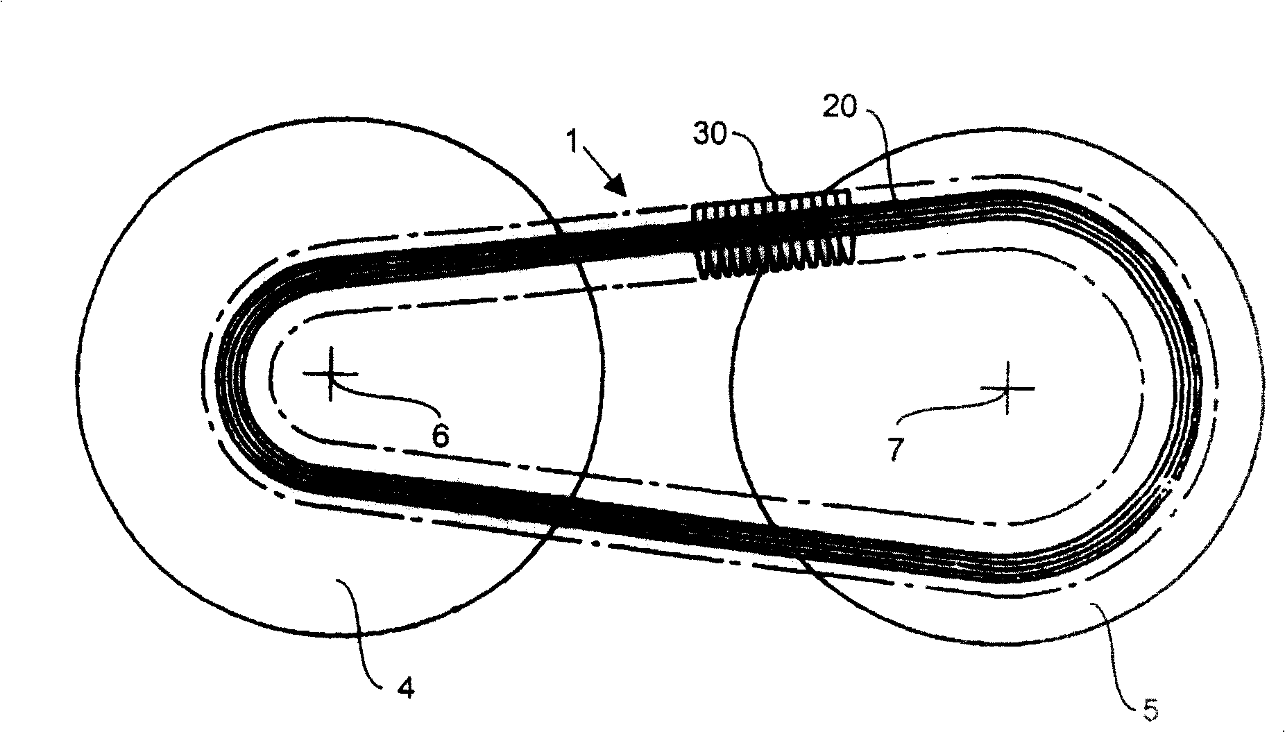
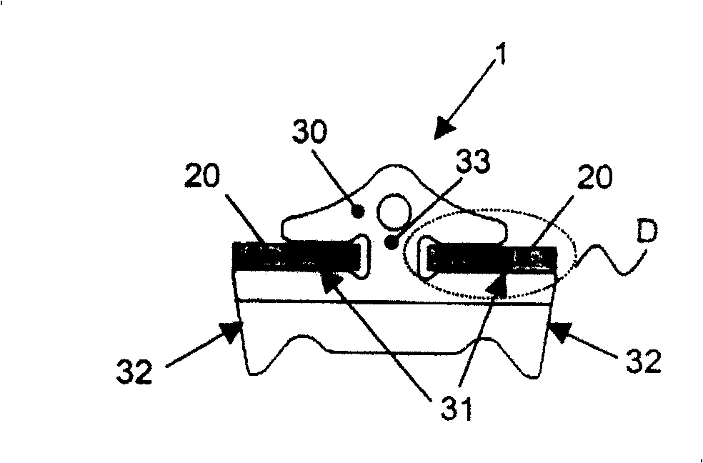
[0024] figure 1 Represents a schematic cross-section of a continuously variable transmission or CVT having a drive belt 1 comprising a tensioning device 20 comprising a number of radially nested, thinner continuous belts shape, so that the stretching device 20 can be relatively easily bent in its longitudinal direction; The innermost strip, this contact surface 31 is hereinafter referred to as the saddle surface 31 . The drive belt 1 is positioned around and between a set of pulley pulleys 4, 5, each pulley having a respective axis of rotation 6, 7. In order to transmit torque between the pulleys 4, 5 by means of friction, the drive belt 1 is clamped to each of the pulleys 4, 5 by moving the sheaves of the pulleys 4, 5 axially towards each other Between the two sheaves of the belt, and then exert a clamping force on the transmission belt 1. In order to carry this clamping force, the crossing elements 30 of the drive belt 1 are provided with sides 32, which are mainly transv...


PUM


Abstract

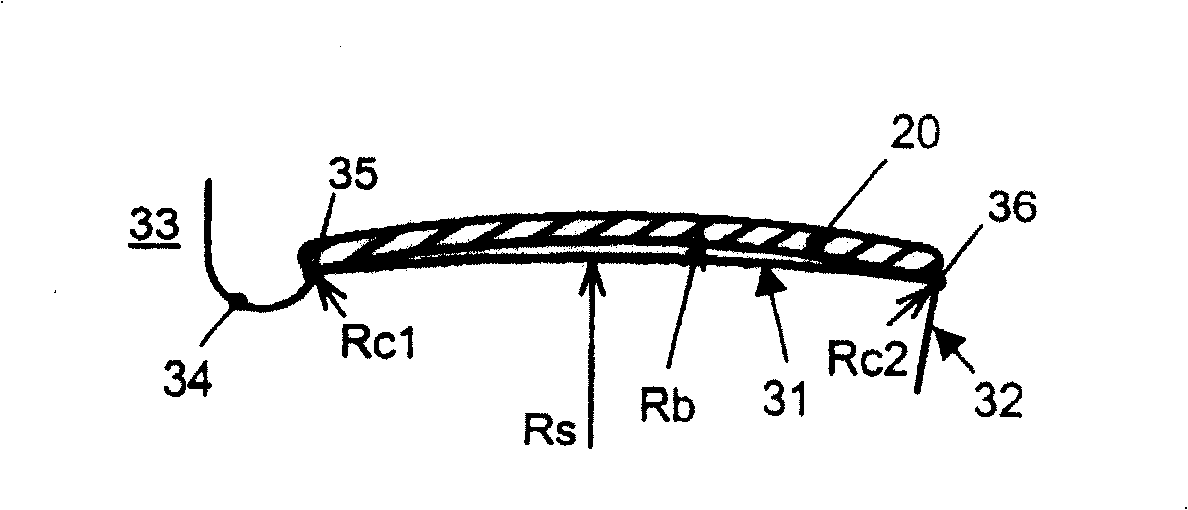
Drive belt (1) comprising at least one continuous band (21) and a number of cross elements (30) having a transversely curved saddle surface (31) of saddle radius (Rs) for interacting with an inwardly oriented main face of the continuous band (21) that at a first lateral side thereof adjacent a pillar part (33) of the element (30) connects to a concavely recessed surface part (34) through a first convexely curved transition surface part (35). The drive belt further incorporating the features that: a transverse width (W) of the continuous band (21) is larger than a transverse width of the saddle surface (31); the saddle radius (Rs) is essentially constant throughout the transverse width of the saddle surface (31); the saddle radius (Rs) is smaller than a so-called band radius (Rb) of a transverse curvature of the band (21) in an unloaded state thereof, irrespective of an amount of bending in the longitudinal direction of the band (21); and the first transition surface part (35) forms a relatively sharp edge. <IMAGE>

Description

technical field [0001] The invention relates to a drive belt for transmission to achieve a continuously variable transmission ratio as stated in the preamble of claim 1 . Background technique [0002] Drive belts of this type are generally known in continuously variable drive applications and are more typically known from the applicant's patent EP-A-1111271. A drive belt consists of one or two tensioning devices, typically in the form of a nested set of continuous metal strips. Continuous belts, currently applied and tested for conveyor belts, have two separate tensioning devices, have a transverse width in the range of 8 to 15 mm, a radial thickness in the range of 0.10 to 0.30 mm, and a longitudinal circumference in the range of 210 to 700 mm. These ranges represent automotive applications for drive belts. The known drive belt is suitable for continuously varying drives in which the belt runs between the frusto-conical sheaves of a pair of adjustable pulleys, whereby the...

Claims


Application Information

Patent Timeline
IPC IPC(8): F16G5/16
CPCF16G5/16
Inventor 明·德·德兰彼得·安东尼厄斯·塞瓦斯蒂亚努斯·马里亚·彭宁斯
Owner ROBERT BOSCH GMBH
Learn More