Direct-fluid-supply writing implement
一种直液式、笔具的技术,应用在书写器具、其他墨水笔、印刷等方向,能够解决廉价提供、不能空气和墨水交替、结构复杂等问题,达到制造容易、简化结构的效果
- Summary
- Abstract
- Description
- Claims
- Application Information
AI Technical Summary
Problems solved by technology
Method used
Image
Examples
no. 1 Embodiment
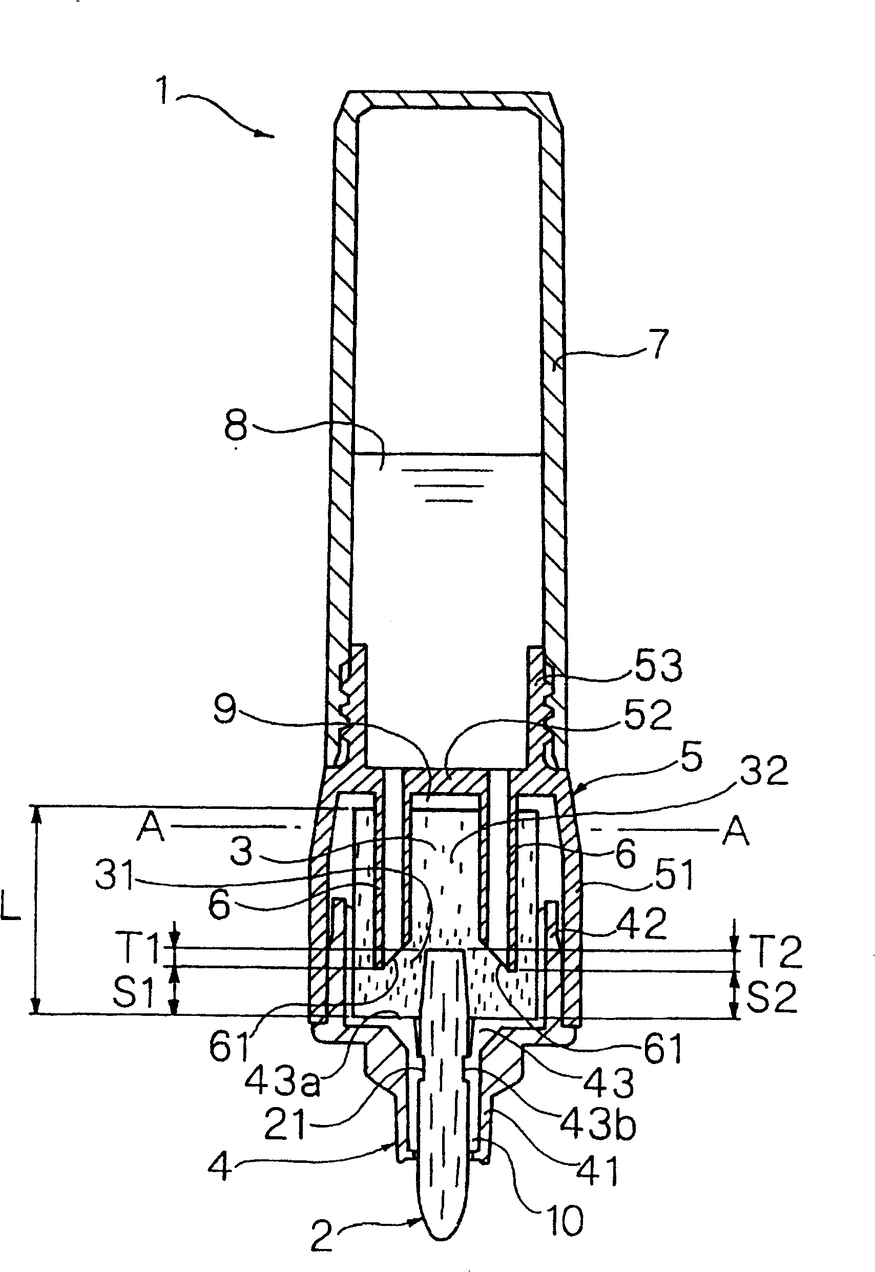
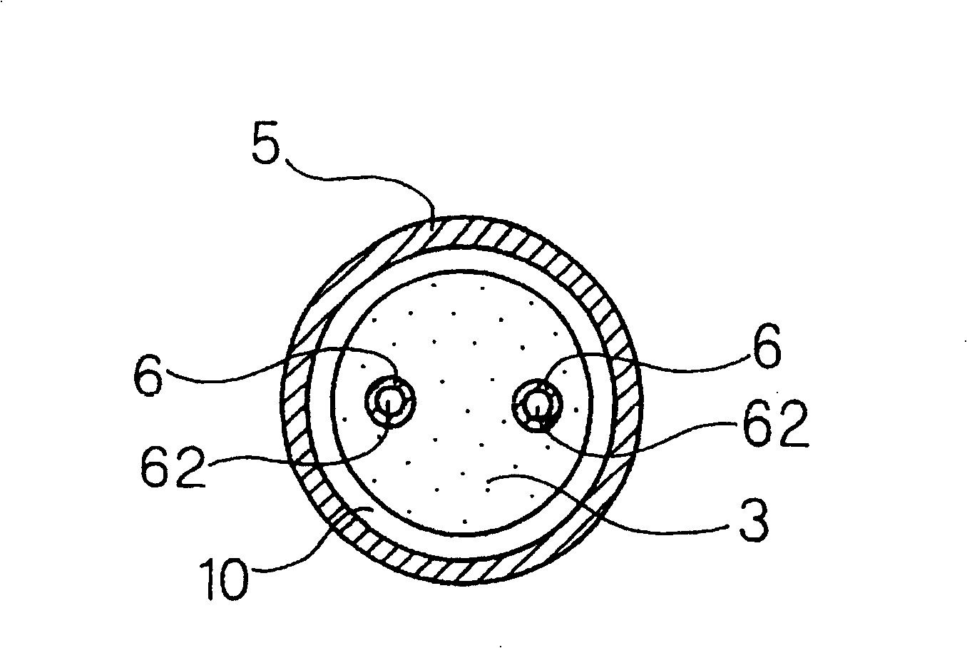
[0163] Figure 1 to Figure 2 A direct fluid writing tool 1 according to a first embodiment of the present invention is shown.
[0164] The direct-liquid pen tool 1 of this embodiment has: a pen tip 2; an ink absorbing body 3 connected to the rear end of the pen tip 2; an absorbing body housing part that holds the above-mentioned pen tip 2 at the front end and accommodates the above-mentioned ink absorbing body 3 inside; The ink tube 7 is installed at the rear of the above-mentioned absorber housing part, and directly stores the ink 8 inside; the partition plate 52 divides the above-mentioned absorber housing part and the above-mentioned ink tube 7; and a plurality of (specifically, two) communication tubes 6, It protrudes forward from the front surface of the above-mentioned partition plate 52 , pierces through and is connected to the inside of the ink absorber 3 . The absorber housing portion has a tip member 4 holding the pen tip 2 and an intermediate member 5 connecting th...
no. 2 Embodiment
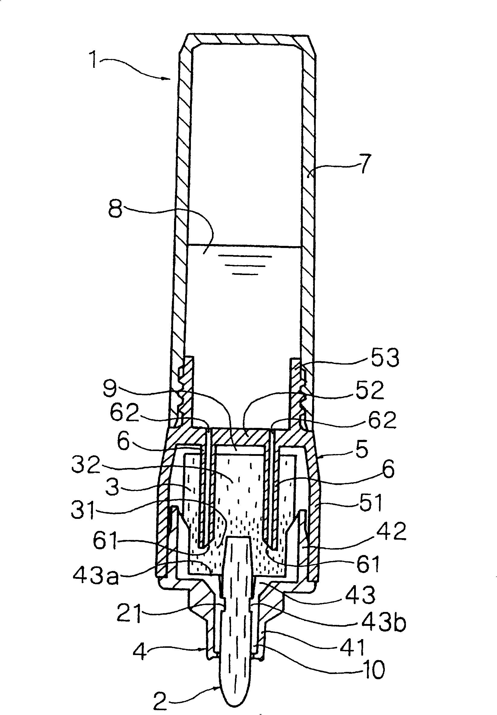
[0187] image 3 Shows the second embodiment of the present invention.
[0188] This embodiment is a modified example of the first embodiment. The difference from the first embodiment is that the high-density portion 31 is formed on the front portion of the ink absorber 3 by pressing and compressing the front outer peripheral surface of the ink absorber 3 inward in the radial direction.
[0189] The diameter of the inscribed circle of the plurality of ribs 43 formed on the inner surface of the large-diameter portion 42 of the front end member 4 is set to be slightly larger than the outer diameter of the front portion of the ink absorber 3 . The above-mentioned ink absorber 3 has a uniform density distribution in the front-rear direction before it is press-fitted into the tip member 4 . In addition, when the front portion of the ink absorber 3 is pressed into the large-diameter portion 42 of the front end member 4, the outer peripheral surface of the front portion of the ink a...
no. 3 Embodiment
[0191] Figure 4 Shows the third embodiment of the present invention.
[0192] This embodiment is a modified example of the first embodiment, and differs from the first embodiment in that a high-density portion 31 is formed at the front of the ink absorber 3 by pressing and compressing the front end of the ink absorber 3 backward.
[0193] On the restricting wall portion 43a of the plurality of ribs 43 formed on the inner surface of the front end member 4, a piercing portion 43c that protrudes large backward is integrally formed. Before the ink absorber 3 is press-fitted into the front end member 4, it has a uniform density distribution in the front-rear direction. And, if the front part of the above-mentioned ink absorbing body 3 is inserted into the large-diameter portion 42 of the above-mentioned front end member 4, the above-mentioned piercing portion 43c is deeply inserted into the front end surface of the above-mentioned ink absorbing body 3, and the front end of the in...
PUM
 Abstract
Description
Claims
Application Information
 - R&D
- Intellectual Property
- Life Sciences
- Materials
- Tech Scout
- Unparalleled Data Quality
- Higher Quality Content
- 60% Fewer Hallucinations
Browse by: Latest US Patents, China's latest patents, Technical Efficacy Thesaurus, Application Domain, Technology Topic, Popular Technical Reports.
© 2025 PatSnap. All rights reserved.Legal|Privacy policy|Modern Slavery Act Transparency Statement|Sitemap|About US| Contact US: help@patsnap.com


