Lock system of closure strucrure for fuel-tank filler pipe

A closing mechanism and closing system technology, applied in the field of locking systems

Inactive Publication Date: 2008-12-31
INERGY AUTOMOTIVE SYST RES (SA)
View PDF4 Cites 0 Cited by
  • Summary
  • Abstract
  • Description
  • Claims
  • Application Information

AI Technical Summary

Problems solved by technology

However, there is also the danger that, in any case, a high-pressure water flow approximately parallel to the axis of the nipple could unlock the locking device in the same way as the fuel injection nipple

Method used


Image

  • Lock system of closure strucrure for fuel-tank filler pipe
  • Lock system of closure strucrure for fuel-tank filler pipe
  • Lock system of closure strucrure for fuel-tank filler pipe

Examples


Embodiment Construction

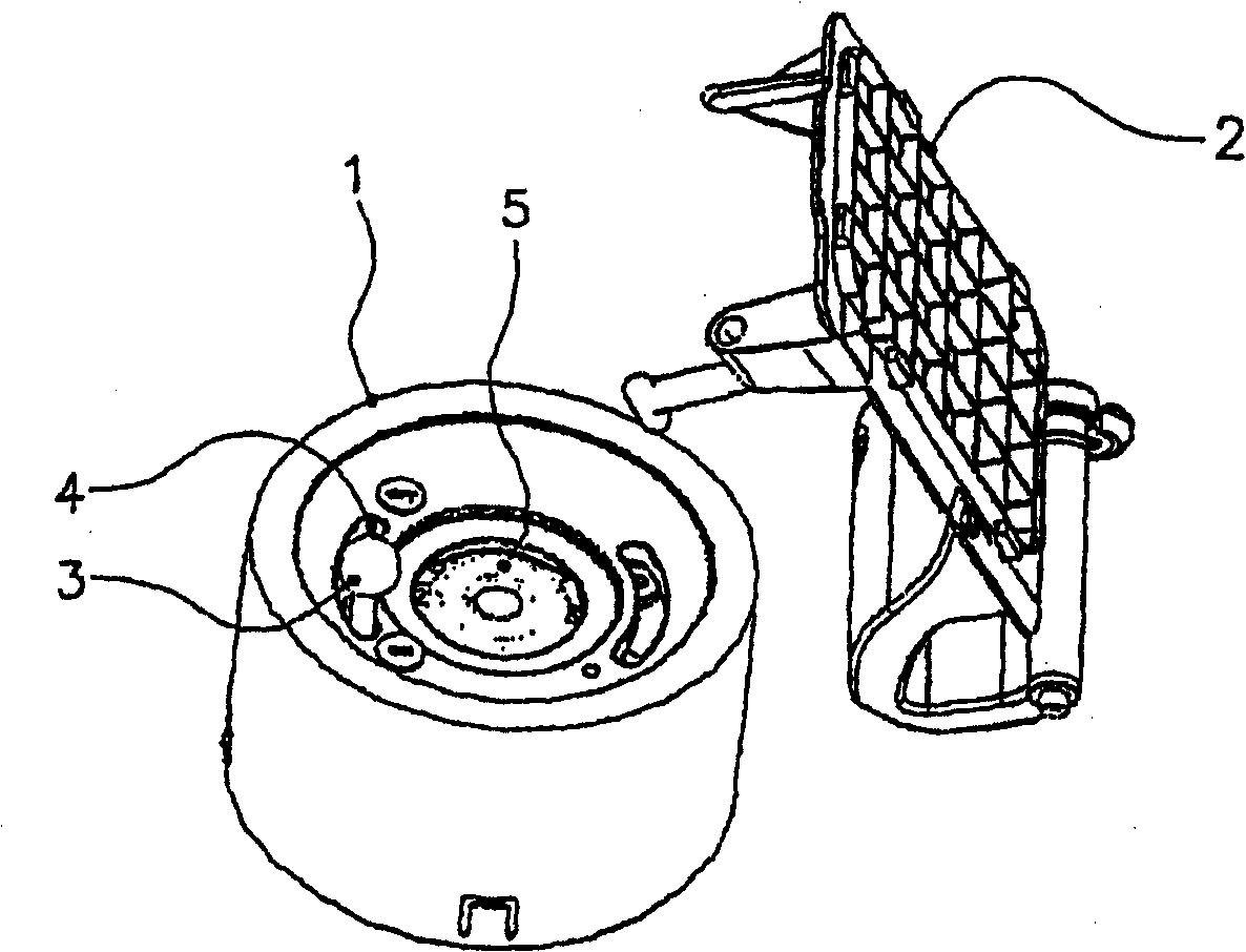
[0038] figure 1 and 2

[0039] These figures show the fitting provided with the closing mechanism 1 and the filler cap 2 in the open position. These elements are provided with a locking system comprising a lever 3 coupled to a turning ring 4 cooperating with the closure 5 by a snap-fit ​​system. The lever 3 slides in a groove 6 formed in the cover 7 . The filling port cap 2 is joined to a joystick arm 8, which in these figures is separate from the joystick.

[0040] exist figure 1 In , the closing mechanism is in the locked position, but the cover 2 has been opened by the user.

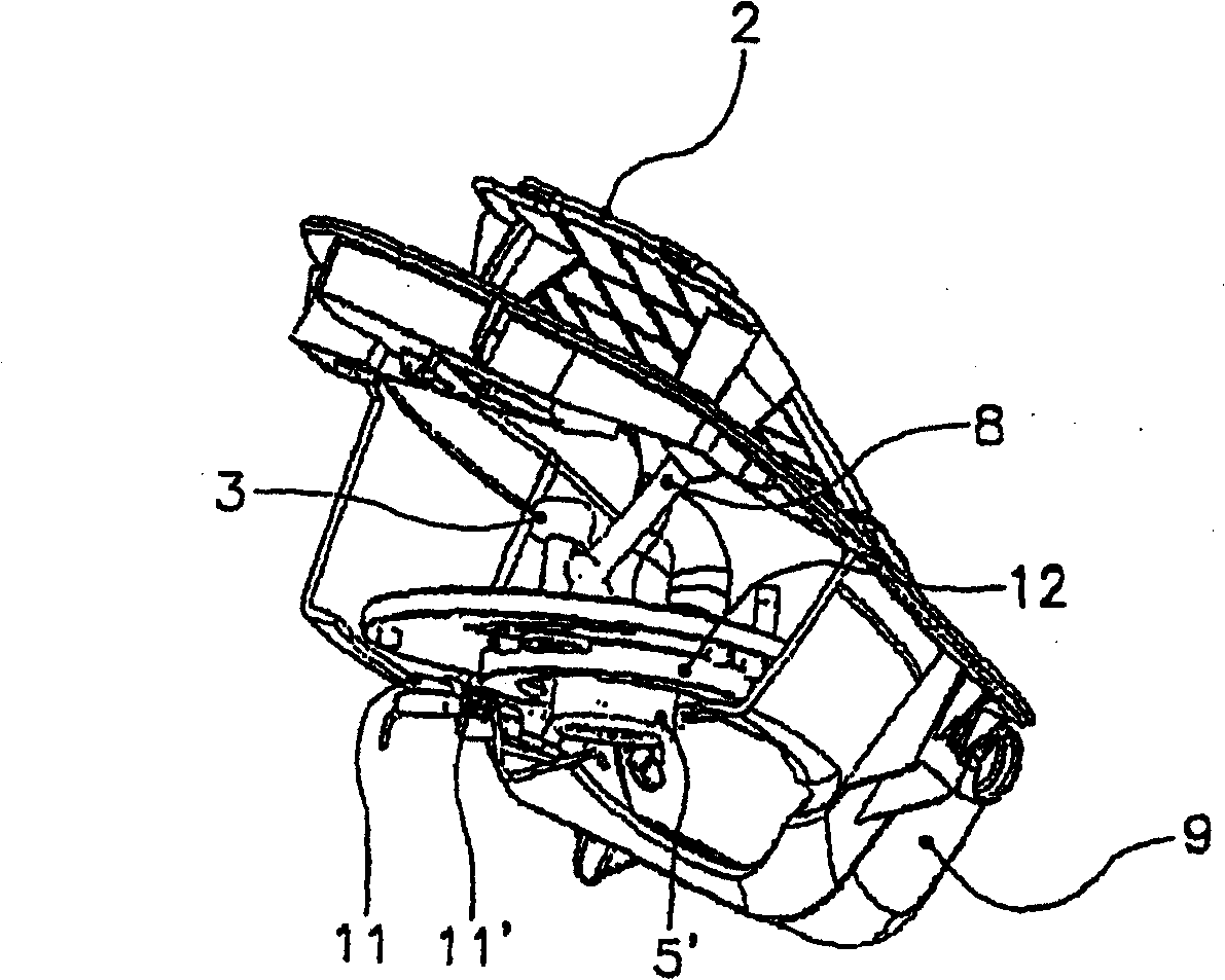
[0041] exist figure 2 In , the closing mechanism has been unlocked by the user either manually acting on the joystick 3 directly or indirectly by controlling an actuator. In this case, the closure 5 is not visible (due to the action of the fuel injection nozzle (not shown), which is in the retracted position to fill the tank).

[0042]Locking the closing mechanism after fuel injection can b...


PUM


Abstract

A system for locking a closure mechanism for a fuel-tank filler pipe covered by a fuel flap, the closure mechanism includes a shutter allowing automatic opening of the pipe via action of a fuel-dispensing nozzle, this shutter being retractable through action of thrust directed against it along an axis parallel to the axis of the pipe head and integral with a return spring allowing it to be held in the closed position. The system includes a lever integral with the closure mechanism and having the effect of locking / unlocking it, depending on its position, and a lever arm, integral with the fuel flap, that can act effectively on the lever only to lock the mechanism when it is unlocked and the fuel flap is being closed.

Description

technical field [0001] The present invention relates to a locking system for a fuel tank filler pipe closing mechanism. Background technique [0002] The filler tube on a fuel tank, particularly a fuel tank mounted on a motor vehicle, is closed during normal use, except during fueling. Closing is usually achieved by means of a cap inserted into the upper part of the fuel tube, while a rotational movement is applied to the cap so as to close the filler tube in a liquid-tight and gas-tight manner. There are various types of caps, made of metal and / or plastic, some seal by tightening a seal to grip the seal, some by turning a key inserted in the center of the outer part of the fuel pipe. [0003] Removing the cap prior to filling the fuel tank and replacing the cap and closing the fill tube after filling is usually done manually by the user or service personnel at the gas station. When the fuel tank is full, the cap may be forgotten and not replaced, with the result that the ...

Claims


Application Information

Patent Timeline
Patent Type & Authority Patents(China)
IPC IPC(8): B60K15/04B60K15/05
CPCB60K15/0406B60K15/05B60K2015/0429B60K15/04
Inventor 帕特里斯·博杜卡蒂·蒂斯林
Owner INERGY AUTOMOTIVE SYST RES (SA)
Why Eureka
Try Eureka