
Melt filter for purifying plastic melts

A technology of melt filter and filter, applied in the field of melt filter for purifying plastic melt, to achieve high pressure effect

Active Publication Date: 2008-12-10
GNEUSS KUNST
View PDF5 Cites 1 Cited by
  • Summary
  • Abstract
  • Description
  • Claims
  • Application Information

AI Technical Summary

Problems solved by technology

[0005] Although DE 4212 928 A1 discloses a relatively large-area cover of the filter plate, there is still a large area of ​​the filter plate that is subjected to the surrounding air during its rotation, so that unwanted changes in the plastic can occur

Method used


Image

  • Melt filter for purifying plastic melts

Examples


Embodiment Construction

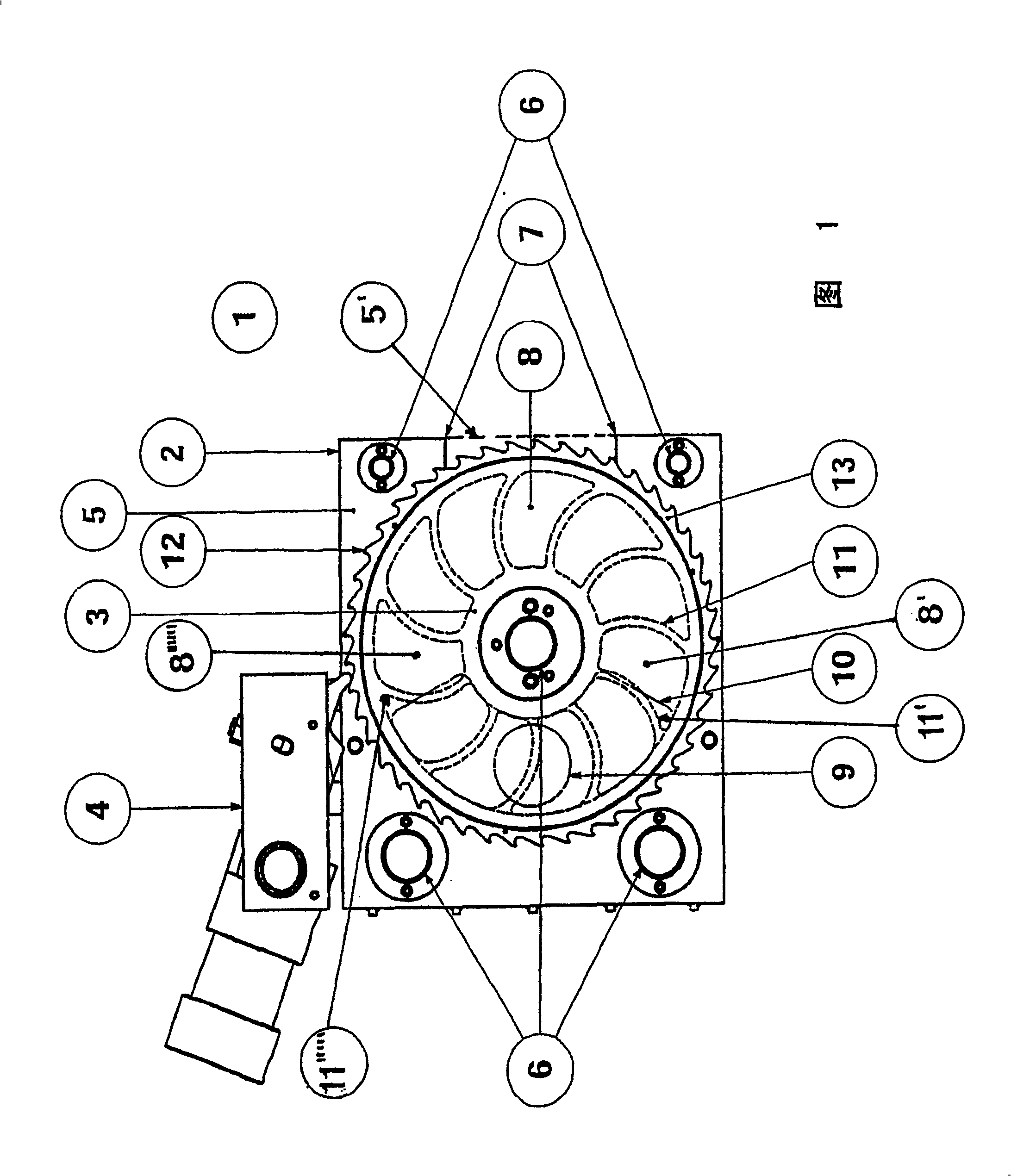
[0013] The present invention is described in detail according to the accompanying drawings. The drawing shows a melt filter 1 consisting of a housing 2 , a filter plate 3 and a pawl drive 4 . The housing 2 consists of a thin plate 5 which is connected by means of connecting elements 6 to a further thin plate 5' indicated in outline with dashed lines. Filter plate 3 is sandwiched between thin plates 5, 5'. Shown in the sheet 5 is a filter element exchange station 7 which is approximately the size of a filter element 8 . The sheet metal 5 also has a melt channel 9 which widens toward the filter plate 3 in the shape of a segment 10 .

[0014] In addition to the filter element 8 , the filter plate 3 has a partition 11 . On the circumference of the filter plate there is a pawl 12 which interacts with the pawl drive 4 . The rim 13 connects the partitions 11 to each other.

[0015] Since the filter element changing station 7 is chosen to be as small as possible, a large part of ...


PUM


Abstract

A melt filter for cleaning a plastic melt issuing from an extruder has a wheel rotatable about an axis and having an outer rim and a plurality of spokes forming an annular array of axially open spaces, a pair of housing plates axially sandwiching and completely covering the wheel and forming offset from the axis a melt passage extending axially through the wheel at the spaces, and removable filter elements braced axially against the wheel at the spaces between the spokes and angularly movable with the wheel with the melt flowing through the filter elements when same are aligned with the passage. One of the plates being formed with an edge cutout. A part on the one housing plate that can cover and close the cutout during normal operation of the melt filter can open and uncover the cutout for changing the filter element aligned axially with the cutout.

Description

technical field [0001] The invention relates to a melt filter for purifying plastic melt, in particular discharged from an extruder, with a filter plate located between two sheets forming a housing provided with a filter element exchange station, Driven in rotation by means of a power-transmitted pawl drive, the filter plate has spaces along a circular belt separated by partitions for accommodating replaceable filter elements, which are overcome by means of perforated plates. The force generated in the direction of flow of the plastic melt due to the pressure drop that occurs on it is supported, and the filter has a melt channel that widens in the direction of the filter element, and the melt channel penetrates in the circular band. Permeate the sheet and add melt to the filter element. Background technique [0002] Melt filters are known, for example, from EP 0 114 651 B1. However, the known melt filters have large and therefore expensive filter plates, their filter eleme...

Claims


Application Information

Patent Timeline
Patent Type & Authority Patents(China)
IPC IPC(8): B29C47/68B29C48/04
CPCB29C48/04B29C48/6914B29B7/58
Inventor S·格诺伊斯D·格诺伊斯
Owner GNEUSS KUNST
Learn More