
Guide reed swing position adjusting device of double raschel machine

A yarn guide bar and adjustment device technology, which is applied in the field of swing position adjustment devices, can solve problems such as the complexity of the yarn guide bar drive mechanism, and achieve the effect of easy adjustment and reduced swing amount

Inactive Publication Date: 2008-11-26
NIPPON MAYER
View PDF4 Cites 12 Cited by
  • Summary
  • Abstract
  • Description
  • Claims
  • Application Information

AI Technical Summary

Problems solved by technology

[0008] However, in the above case, 2-3 rotatable support shafts for swinging are required, and for each support shaft, a lot of installation space such as a bearing bush for holding the support shaft is required, or in order to give the support shaft rotation Displacement, it is necessary to set a driving rod on each supporting shaft, and at the same time, a series of arms, rods, cams, etc. attached to each supporting shaft are required. More driving parts, it is undeniable that the driving mechanism of this guide bar is very complicated

Method used


Image

  • Guide reed swing position adjusting device of double raschel machine
  • Guide reed swing position adjusting device of double raschel machine
  • Guide reed swing position adjusting device of double raschel machine

Examples


Embodiment Construction

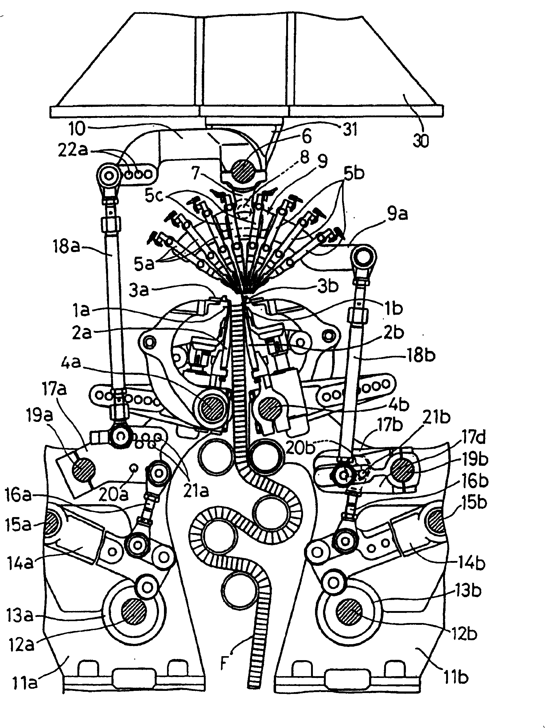
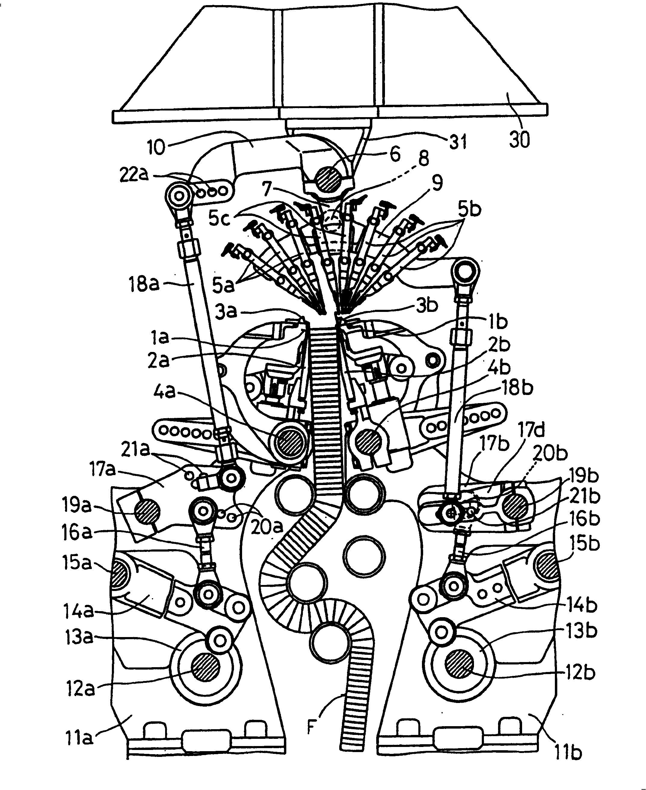
[0023] Next, according to the embodiment shown in the drawings, the embodiment of the device for adjusting the swinging position of the guide bar in the double-needle bed Raschel warp knitting machine of the present invention will be described.

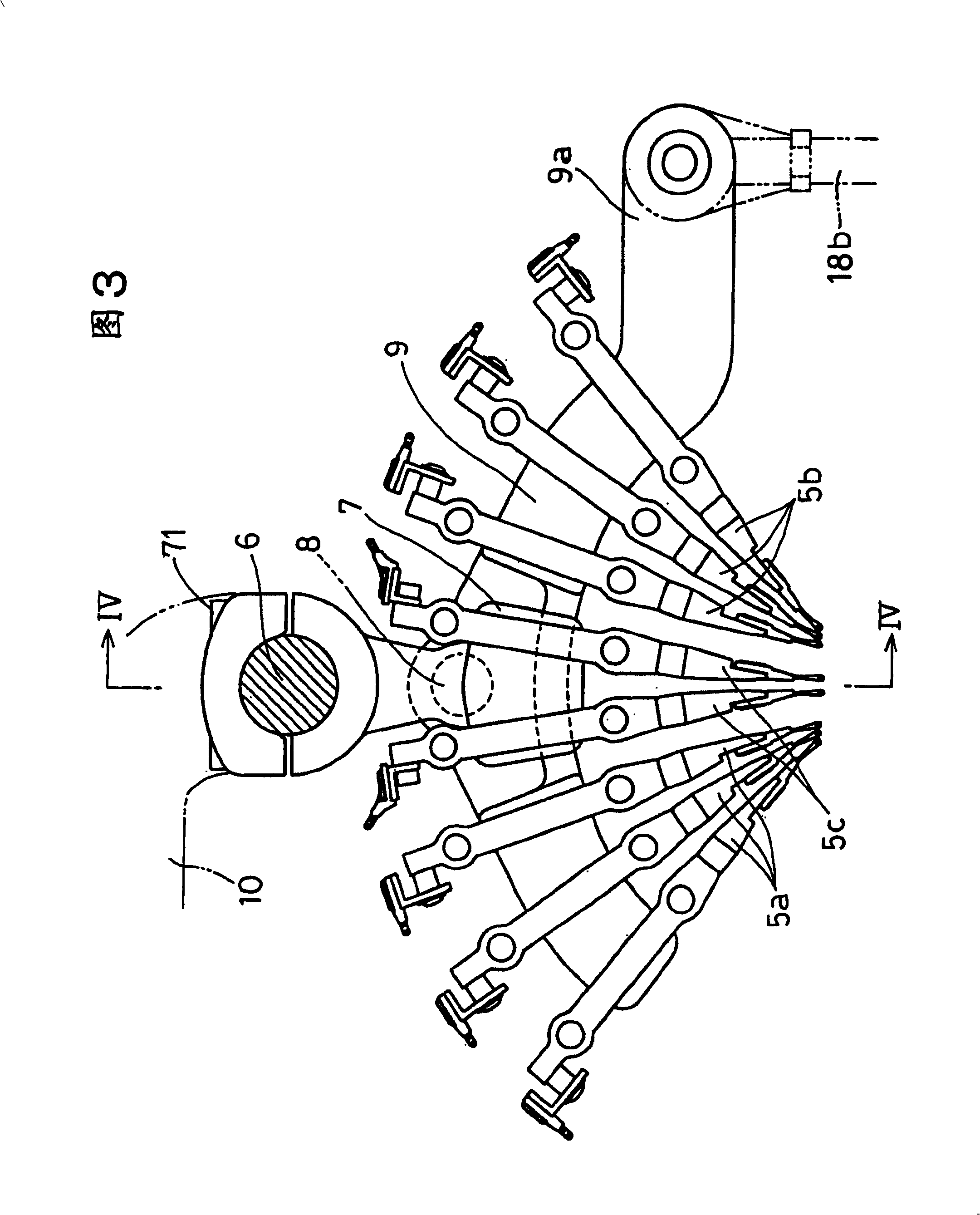
[0024] figure 1 It is a schematic cross-sectional view of a double-needle-bed Raschel warp knitting machine, seen from the side, showing a swing position adjusting device for a guide bar of the present invention, figure 2 It is a cross-sectional view of the double-needle bed Raschel warp knitting machine as above, when the needle cylinder interval, that is, the interval between the front and rear needle groove plates, is enlarged. Fig. 3 is the enlarged sectional view of the guide bar part of the device of the previous figure, Figure 4 It is a partial cross-sectional view of line IV-IV in the preceding figure.

[0025] In the figure, 1a is the row of knitting needles at the front, and 1b is the row of knitting needles at the rear,...


PUM


Abstract

A guide reed swing position adjusting device of a double raschel machine capable of facilitating the adjustment of a swing position by simplifying the structure of the guide reed drive mechanism of the double raschel machine to suppress the excessive swing motion of a guide reed when a broad texture is knitted, wherein the guide reed having front ground yarn reeds (5a), connecting yarn reeds (5c), and rear ground yarn reeds (5b) is installed against front and rear two rows of needle rows (1a) and (1b), a means for causing and synthesizing a swing displacement other than the swing of the front and rear ground yarn reeds in synchronism with the swing of the connecting yarn reeds, and a swing displacement independent of the swing displacement of the connecting yarn reeds is added to the front and rear ground yarn reeds so that the positions of the front and rear ground yarn reeds acting on the needle rows can be adjusted.

Description

technical field [0001] The invention relates to a device for adjusting the swing position of a guide bar in a double-needle bed Raschel warp knitting machine. Background technique [0002] In the past, when a double-faced warp knitted product was knitted by a double-needle bed Raschel warp knitting machine having two rows of knitting needle rows, the guide bar provided corresponding to the two rows of knitting needles would have a corresponding to each knitting needle. The needle hooks of the rows perform a swinging movement in the front-back direction of the knitting machine in order to carry out the erection operation of the knitting yarn for forming the stitches. [0003] The amplitude of the oscillating motion of the guide bar is different due to the difference in the interval between two opposing knitting needle rows or the difference in knitting structure. [0004] Above the row of knitting needles, a plurality of yarn guide bars with various functions are arranged. ...

Claims


Application Information

Patent Timeline
Patent Type & Authority Patents(China)
IPC IPC(8): D04B27/26
CPCD04B27/26D04B23/02
Inventor 野坂训正立松正治
Owner NIPPON MAYER
Learn More