
Structure of electric connection

A technology of electrical connection and structure, applied in connection, flexible/rotatable wire connectors, circuits, etc., can solve problems such as cable obstruction

Inactive Publication Date: 2008-09-24
BENQ CORP
View PDF4 Cites 0 Cited by
  • Summary
  • Abstract
  • Description
  • Claims
  • Application Information

AI Technical Summary

Problems solved by technology

Most of the circuit boards in the screen and the circuit boards on the device body are electrically connected by cables. Therefore, when the screen rotates to a certain angle, it will be hindered by the cables, so it can only rotate within a certain range of angles. Some There are even directional restrictions, such as only clockwise or counterclockwise rotation, which are due to the restrictions caused by the electrical connection structure it adopts

Method used


Image

  • Structure of electric connection
  • Structure of electric connection
  • Structure of electric connection

Examples


Embodiment Construction

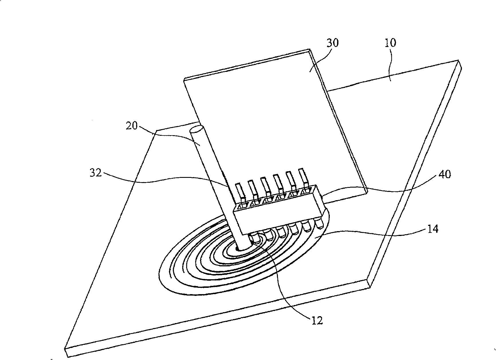
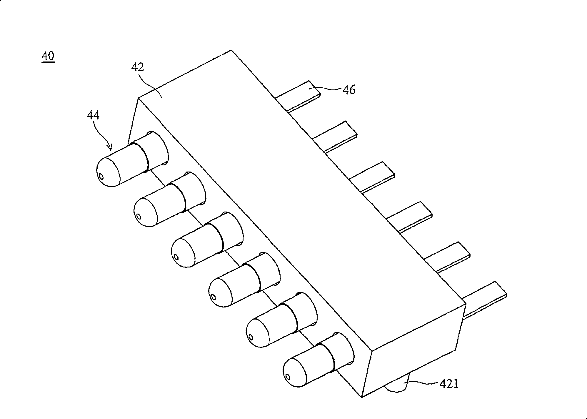
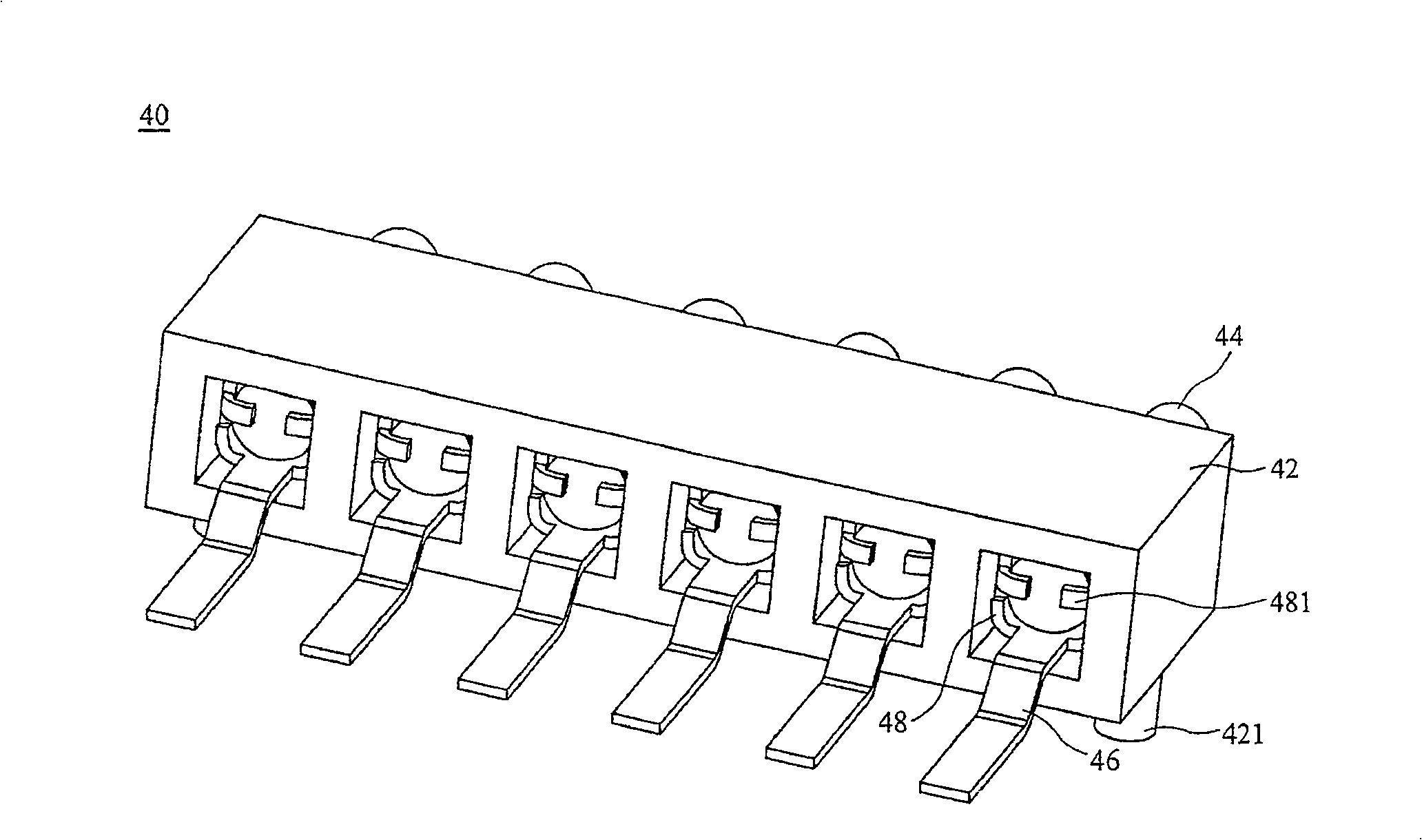
[0019] figure 1 It is a perspective view of a preferred embodiment of the electrical connection structure of the present invention. The electrical connection structure of the present invention includes a first circuit board (first electronic component) 10 , a shaft 20 , a second circuit board (second electronic component) 30 and a connector 40 . A shaft hole 12 is defined on the first circuit board 10 , the shaft body 20 is pivoted on the first circuit board 10 through the shaft hole 12 , and the second circuit board 30 is connected to the shaft body 20 by a connecting piece 32 . The connector 40 is arranged on the second circuit board 30 and is electrically connected with the circuit on the second circuit board 30. When the second circuit board 30 rotates around the shaft body 20, the connector 40 is connected to the first circuit board 10. Contact is maintained, thereby maintaining the electrical connection between the first circuit board 10 and the second circuit board 30 ...


PUM


Abstract

The invention relates to an electric connecting structure, which comprises the first electric element, an axial element, the second electric element and a connector. Wherein, the axial element is axially connected to the first electric element; the second electric element is combined to the axial element; the connector is on the second electric element to contact the first electric element; when the second electric element rotates around the axial element, the connector contacts the first electric element all the time, to connect the first electric element and the second electric element.

Description

technical field [0001] The present invention relates to a structure for electrical connection, in particular to a structure for continuously maintaining electrical connection between two electronic components during relative rotation. Background technique [0002] Mobile phones or photography devices usually have screens, and in some novel designs, these screens can be rotated for ease of use. Most of the circuit boards in the screen and the circuit boards on the device body are electrically connected by cables, so when the screen rotates to a certain angle, it will be hindered by the cables, so it only rotates within a predetermined angle range, and some There are even directional restrictions, such as clockwise or counterclockwise rotation, which are all due to the restrictions caused by the electrical connection structure adopted. Contents of the invention [0003] In view of this, the purpose of the present invention is to provide an electrical connection structure, s...

Claims


Application Information

Patent Timeline
Patent Type & Authority Patents(China)
IPC IPC(8): H01R35/00
Inventor 林晁雍杨胜迪
Owner BENQ CORP
Learn More