Electric flow control valve

A flow control valve, electric technology, applied in heating and ventilation control systems, refrigerators, valve devices, etc., can solve the problem that the rotor 33 cannot rotate, and achieve the effect of improving reliability

Inactive Publication Date: 2008-09-24
FUJIKOKI MFG CO LTD
View PDF6 Cites 0 Cited by
  • Summary
  • Abstract
  • Description
  • Claims
  • Application Information

AI Technical Summary

Problems solved by technology

[0016] However, the stop member 38 is made of stainless steel, for example, has elasticity, and there is no problem when the valve opening restriction pin 37 abuts against the side of the stop member 38. bottom surface, the stopper 38 is fixedly connected with the valve-opening limiting pin 37, resulting in the discomfort that the rotor 33 cannot rotate in the valve-closing direction.

Method used


Image

  • Electric flow control valve
  • Electric flow control valve
  • Electric flow control valve

Examples


Embodiment Construction

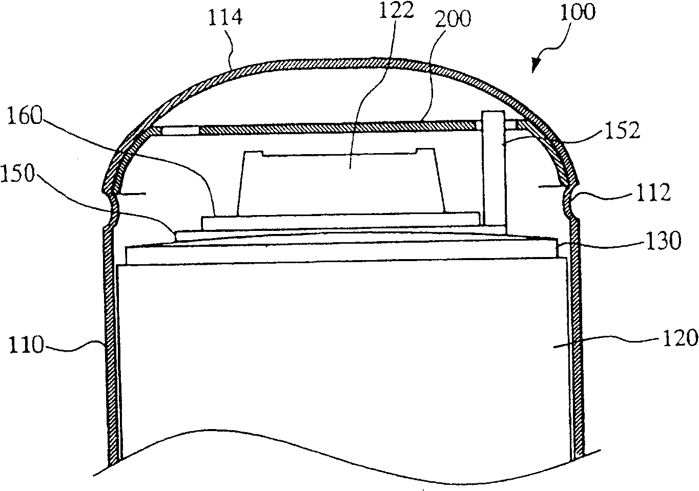
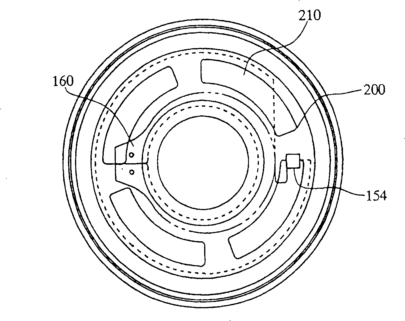
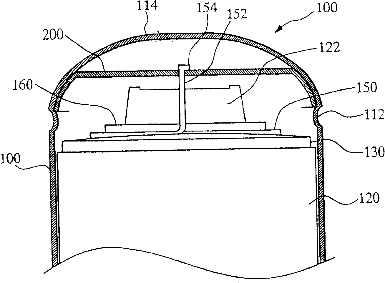
[0046] Hereinafter, embodiments of the present invention will be described with reference to the drawings. 1 and 2 are diagrams showing main parts of an electric flow control valve 100 according to this embodiment, and Figure 6 The existing electric flow control valve shown also shows the upper structure of the rotor 120 formed by the sleeve and the magnet, and the basic structure and function are the same as those of the rotor 120. Figure 6 The conventional electric flow control valve shown is the same, and only the above-mentioned rotor is shown in FIG. 1 and FIG. 2 because only the upper structure of the rotor equipped with the limiter is different. In addition, Fig. 1 shows the structural diagram (a) and the upper surface diagram (b) of the top 114 structure of the airtight casing of the electric flow control valve, and Fig. 1 (b) shows that the top 114 of the airtight casing of Fig. 1 (a) is halfway The top view of the cut state. And Fig. 2 shows the structural diagram ...


PUM


Abstract

To improve a structure for restricting a rising position of a rotor of an electric flow rate control valve having the rotor inside of a sealed case and a coil outside of the sealed case. This electric flow rate control valve 100 has the rotor 120 in the sealed case 110. The rotor 120 is fixed to a sleeve 122. The sleeve 122 is engaged with a fixed screw part, and the rotor 120 is vertically moved in accompany with the rotation. When the rotor 120 is raised to the limit, a stopper 152 mounted on the rotor 120 is brought into contact with a stop plate 200 mounted inside of the sealed case 110 to restrict the rotation.

Description

technical field [0001] The present invention relates to an electric flow control valve, and more particularly to an electric flow control valve for controlling the flow rate of refrigerant fluid used in refrigeration cycles such as refrigeration. Background technique [0002] The existing electric flow control valve used in the refrigeration cycle is composed of a valve body having a valve seat and a valve body in the valve chamber, and a motor such as a stepping motor arranged on the upper part of the valve body. The airtight case, the stator coil arranged outside the airtight case, and the rotor arranged in the inner chamber of the airtight case. The rotor is formed of, for example, an aluminum sleeve disposed on the inner peripheral side, and a magnet such as ferrite disposed on the outer peripheral side. [0003] In addition, a long rod-shaped valve shaft extends from within the airtight housing through the valve chamber, one end of which is slidably secured to the slee...

Claims


Application Information

Patent Timeline
Patent Type & Authority Patents(China)
IPC IPC(8): F16K31/04F24F11/02F25B41/06
CPCF25B2341/065F25B41/062Y02B30/72Y02B30/70F25B41/34F25B41/35F24F13/222
Inventor 饭田健词伊东雅晴梅泽仁志
Owner FUJIKOKI MFG CO LTD
Why Eureka
Try Eureka