Thermal-drive solution ventilation processor set by using cooling water as cooling source

A technology for fresh air treatment unit and cooling water, applied in the energy field

Active Publication Date: 2008-09-10
TSINGHUA UNIV +1
View PDF4 Cites 0 Cited by
  • Summary
  • Abstract
  • Description
  • Claims
  • Application Information

AI Technical Summary

Problems solved by technology

Change cooling water to hot water in winter

Method used


Image

  • Thermal-drive solution ventilation processor set by using cooling water as cooling source
  • Thermal-drive solution ventilation processor set by using cooling water as cooling source
  • Thermal-drive solution ventilation processor set by using cooling water as cooling source

Examples


Embodiment Construction

[0014] Below in conjunction with accompanying drawing, technical scheme of the present invention will be further described;

[0015] please see Figure 1~3 .

[0016] The fresh air unit to achieve this performance has the following three processes;

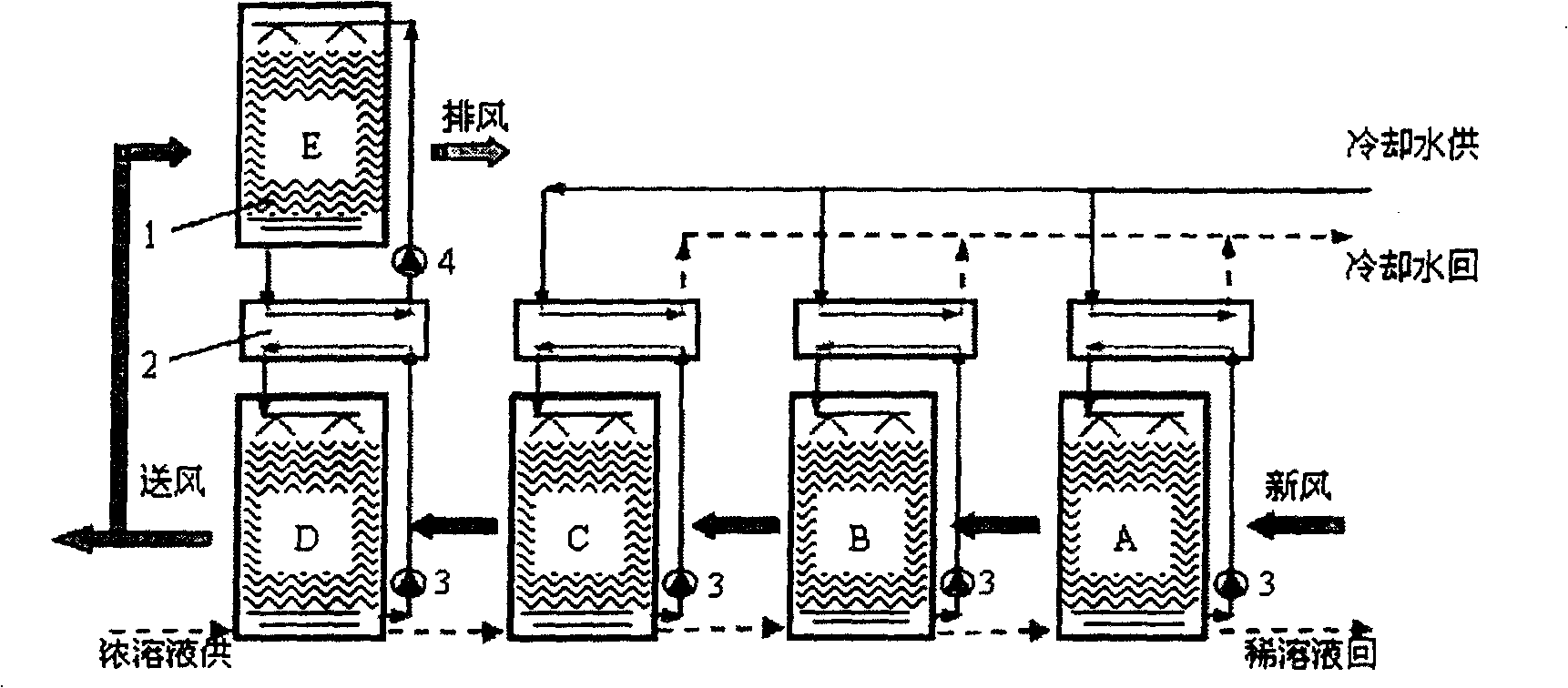
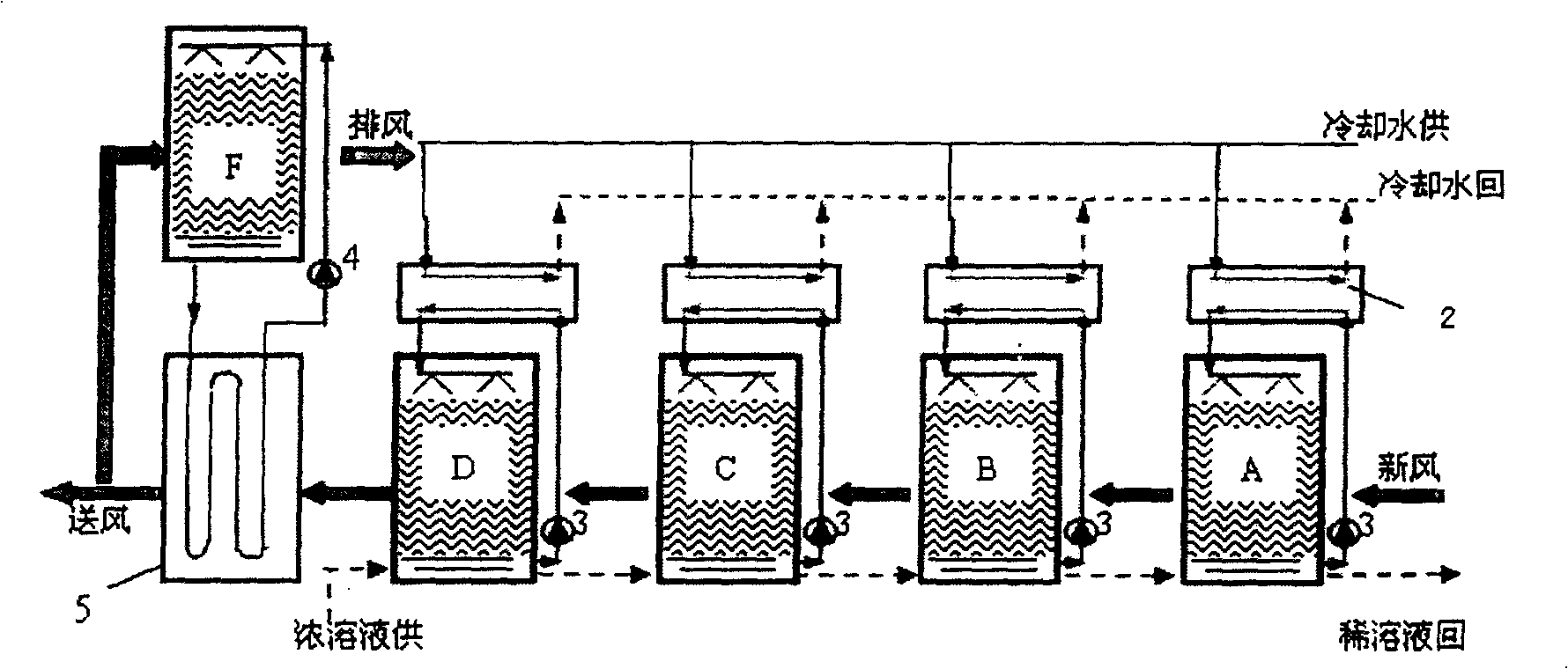
[0017] Process 1: A fresh air treatment unit that uses indirect evaporative cooling to cool down the solution

[0018] The fresh air processor consists of two parts: a four-stage unit spray module and a one-stage direct evaporative cooling device. The unit spray module is composed of four plate heat exchangers 2, solution-air gas-liquid direct contact modules A, B, C, D and four solution self-circulation pumps. The direct evaporative cooling device consists of a water-air gas-liquid direct contact module E, a water pump 4 and other components (see figure 1 ).

[0019] Its working process is as follows:

[0020] In the unit spray module, there are four solution self-circulation pumps to control the flow of the spray solution ...


PUM


Abstract

The invention relates to a thermal-driving solution fan which uses cooling water as cold source. Wherein, it is characterized in that: said device is formed by a unit spray module, and a direct vaporize cooler; said unit spray module comprises a sheet heat exchanger 2, gas-liquid direct contact modules (A-D) and solution self-circulate pump3; said direct vaporize cooler comprises a gas-liquid direct contact module E and a water pump 4; the solution self-circulate pump controls the fluxes of sprayed solutions inside the modules (A-D); another system circulate pump controls the flux of dense solution between the modules (A-D); since the invention uses cooling water as cold source to remove the hidden head in humidification, and uses dense solution to obtain dry wind via multistage dehumidify modules, and uses indirect vaporizing cooling technique to obtain certain wind temperature.

Description

technical field [0001] The invention relates to a heat-driven solution fresh air treatment unit using cooling water as a cold source in the field of HVAC, and belongs to the field of energy technology. Background technique [0002] The task of the fresh air unit is to realize the process of cooling and dehumidifying the fresh air in summer and heating and humidifying the fresh air in winter. In the traditional air-conditioning system, the condensation dehumidification method is adopted, that is, the temperature of the air is lowered to below the dew point by using 7°C chilled water through the surface cooler to condense moisture, thereby dehumidifying the air. Since the dehumidification and cooling of conventional fresh air fans are carried out at the same time, many problems have been brought about: the refrigerator works at a low evaporation temperature, resulting in a low coefficient of performance of the refrigerator; although the air humidity after condensation and dehu...

Claims


Application Information

Patent Timeline
Patent Type & Authority Patents(China)
IPC IPC(8): F24F3/14F24F12/00
Inventor 江亿谢晓云刘晓华刘拴强唐艺丹陈晓阳
Owner TSINGHUA UNIV
Why Eureka
Try Eureka