Micro flow control chip capillary electrophoresis negative pressure sampling method
A microfluidic chip and sample injection technology, applied in separation methods, chemical instruments and methods, material analysis by electromagnetic means, etc., can solve the problems of high voltage in infusion equipment, affecting safe operation, etc., to avoid discrimination effect. , the effect of improving safety and increasing the injection speed
- Summary
- Abstract
- Description
- Claims
- Application Information
AI Technical Summary
Problems solved by technology
Method used
Image
Examples
Embodiment 1
[0018] The steps of the microfluidic chip negative pressure sampling capillary electrophoresis analysis method of the present invention are as follows:
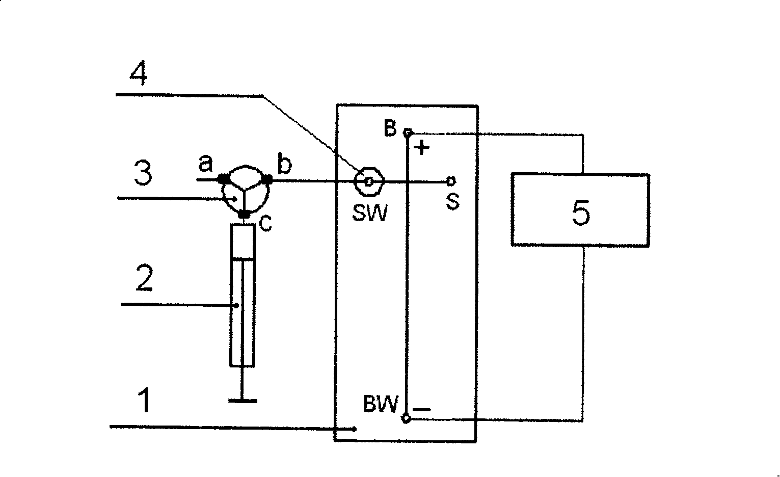
[0019] The diagram of the device for capillary electrophoresis separation of negative pressure injection microfluidic chip is shown in figure 1 . Among them, 1 represents the microfluidic chip, the channel between B and BW on the microfluidic chip is the separation channel, the channel between S and SW is the sampling channel, and B, BW, S and SW represent buffer reservoirs respectively , buffer waste liquid reservoir, sample liquid reservoir and sample waste liquid reservoir. 2 represents the syringe pump, 3 is the three-way valve, 4 is the interface, and 5 is the high-voltage power supply. Add the sample solution to the sample reservoir S on the microfluidic chip, add different volumes of electrophoresis buffer to the other reservoirs B, SW, and BW, and keep the liquid levels of the reservoirs B and BW at both ends of the...
Embodiment 2
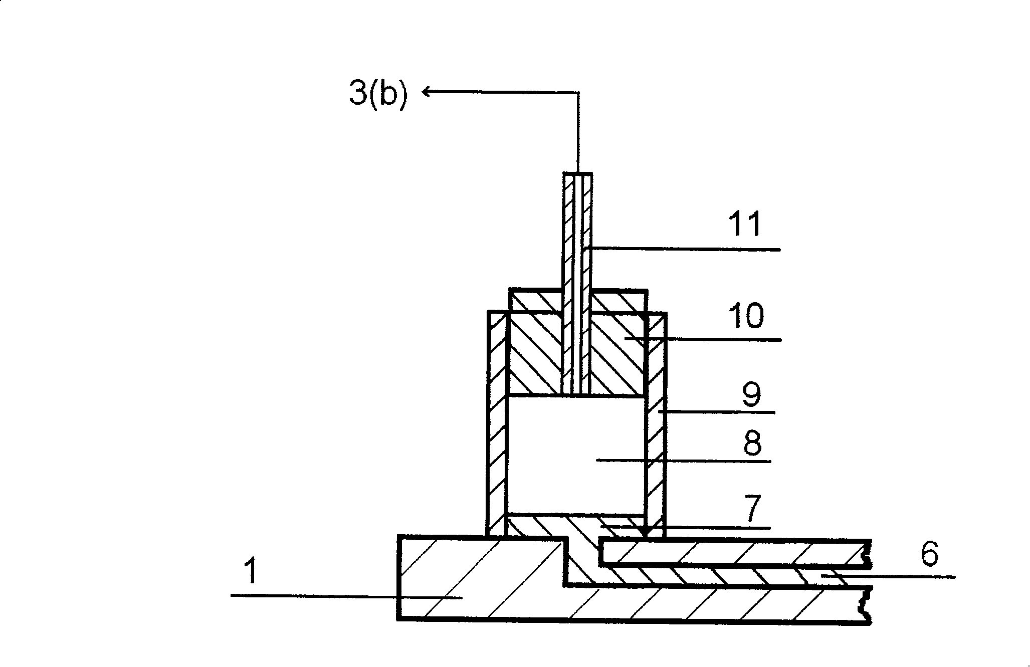
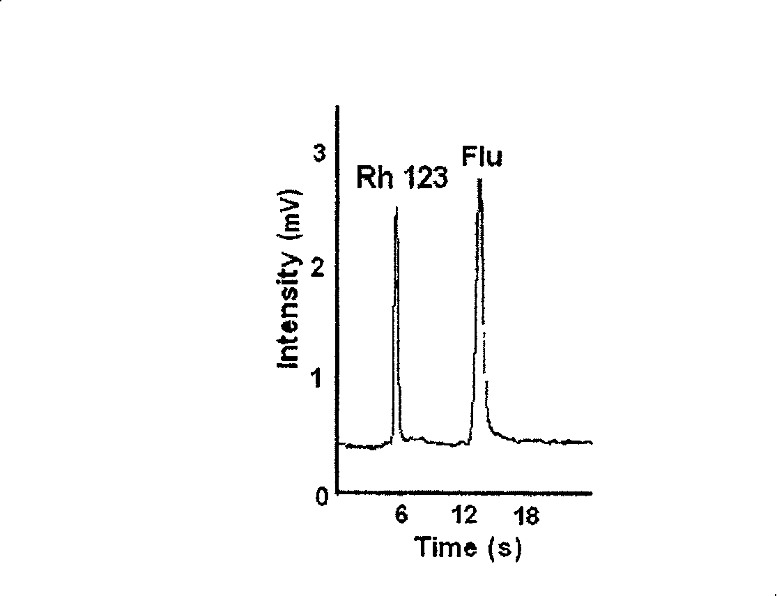
[0022] Provide a more specific optimization instance according to embodiment 1, see figure 1 , the width of the channel on the microfluidic chip is 10-100 μm, and the depth is 5-50 μm. The channel between S and SW is the sampling channel with a length of 5-50 mm. The channel between B and BW is the separation channel with a length of 10-100mm. The separation channel and the injection channel cross each other, or have a double T structure. Drill small holes at both ends of the sampling channel and the separation channel, and use adhesive to bond the micro plastic liquid storage tank on the small holes. The outer diameter of the plastic liquid storage tank is 6mm, the inner diameter is 4mm, and the height is 6mm. S, SW, B, and BW represent the sample liquid storage pool, the sample waste liquid storage pool, the buffer liquid storage pool, and the buffer liquid waste liquid storage pool, respectively. Add 150 μL of 20 mmol / L borax buffer solution with pH 9.2 to reservoir B and...
PUM
 Abstract
Description
Claims
Application Information
 - R&D
- Intellectual Property
- Life Sciences
- Materials
- Tech Scout
- Unparalleled Data Quality
- Higher Quality Content
- 60% Fewer Hallucinations
Browse by: Latest US Patents, China's latest patents, Technical Efficacy Thesaurus, Application Domain, Technology Topic, Popular Technical Reports.
© 2025 PatSnap. All rights reserved.Legal|Privacy policy|Modern Slavery Act Transparency Statement|Sitemap|About US| Contact US: help@patsnap.com


