
Implementing method of intelligent flow control valve and valve

A technology of intelligent fluid and realization method, applied in the direction of adaptive control, general control system, control/regulation system, etc., can solve the limited control range of dynamic working pressure difference, high overall pressure loss at both ends of the valve, and the starting point of working pressure difference High problems, to achieve long service life, large flow capacity, mechanical structure and simple effect

Active Publication Date: 2008-06-11
HANGZHOU ZETA TECH
View PDF4 Cites 0 Cited by
  • Summary
  • Abstract
  • Description
  • Claims
  • Application Information

AI Technical Summary

Problems solved by technology

[0004] The latest products of dynamic balance electric valves generally adopt the principle of spring mechanical self-reliance, so there are small flow capacity, limited dynamic working pressure difference control range, inflexible application, high starting point of working pressure difference, high overall pressure loss at both ends of the valve, etc. Disadvantages (since DP=DP 1 +DP 2 , in actual use, the pressure of the differential pressure controller must be sacrificed to maintain the differential pressure of the electric control valve, such as DP 1 constant, obviously sacrificing the pressure of the differential pressure controller is also a waste of energy)

Method used


Image

  • Implementing method of intelligent flow control valve and valve
  • Implementing method of intelligent flow control valve and valve
  • Implementing method of intelligent flow control valve and valve

Examples


Embodiment Construction

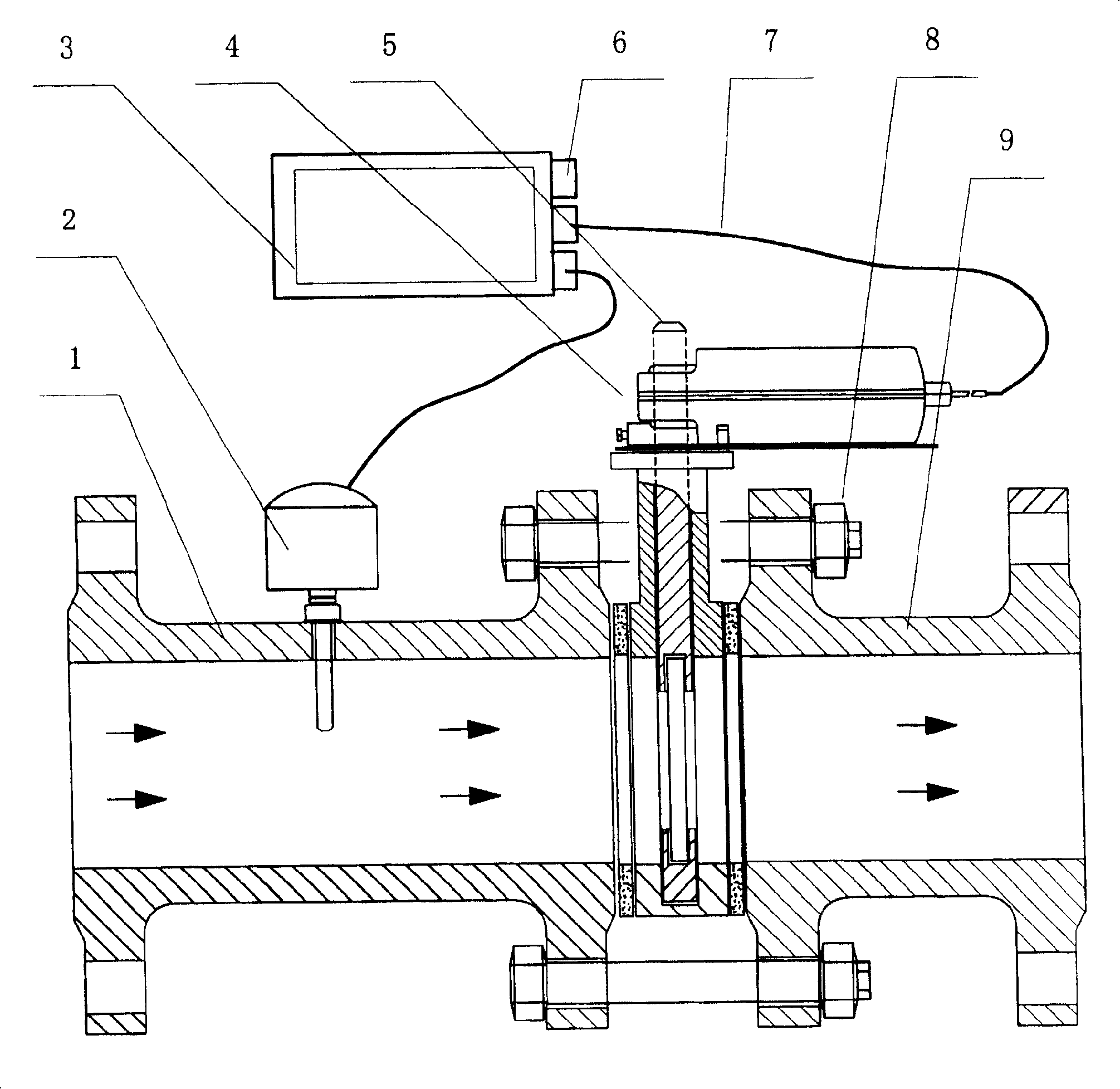
[0038] Reference attached figure 1 , the present invention will be described in detail below.

[0039] The figure shows an intelligent fluid control valve, which includes an electric valve body assembly 2 and an analog electric actuator 4 connected to the electric valve body assembly 2 for implementing analog adjustment of the electric valve body. The front valve body flow tube 1, the electric valve body assembly 2, and the rear valve body flow tube 1 are sequentially connected by bolts / screw cap standard parts 8, or assembled into one body.

[0040] The insertion type flow sensor 2 is installed on the wall surface of the front valve body flow tube 1 by fitting and inserting. The flow sensor 2 , the intelligent controller 3 , and the analog electric actuator 4 are sequentially connected through a cable 7 , and the analog electric actuator 4 is assembled on the electric valve body assembly 5 .

[0041] The electric valve body assembly 2 is an electric regulating butterfly val...


PUM


Abstract

The present invention relates to an intelligent control implement method of valve and its valve. Said invention is aimed at providing an implement method of intelligent fluid control valve based on high-level calculation and its valve. Said method includes the following steps: setting flow value in intelligent controller, data sampling external signal and comparing it with set value, utilizing APID algorithm to regulate opening of electric valve component so as to implement intelligent control. Said control valve includes valve body and electric valve component placed in said valve body interior, and said electric valve component includes flow sensor, intelligent controller and electric executor, etc.

Description

technical field [0001] The invention relates to a valve intelligent control realization method and a valve. More specifically, the present invention relates to a realization method and valve of an intelligent fluid control valve based on advanced calculation. Background technique [0002] Hydraulic imbalance is common in the water system pipe network. The hydraulic imbalance of the pipe network will easily lead to the waste of system energy and the increase of equipment operation noise. The fluid control valve with advanced intelligent dynamic flow balance function is the solution to the hydraulic balance of complex pipe networks. best means. [0003] The dynamic flow balance electric control valve commonly used at present is essentially a pressure-independent electric valve with mechanical self-operated pressure difference automatic control function. The principle of dynamic balance is relatively simple, that is, integrated or combined dynamic balance electric valve. The ...

Claims


Application Information

Patent Timeline
Patent Type & Authority Patents(China)
IPC IPC(8): G05B13/04
Inventor 沈新荣黎焱朱文斌章威军杨春节郁辉球
Owner HANGZHOU ZETA TECH
Learn More