Vertical shaft high power wind-driven generator

A wind turbine and high-power technology, which is applied to wind turbine components, wind turbines, wind turbine combinations, etc., can solve the problems of high cost and low utilization rate of wind energy, and achieve low friction loss, high utilization rate of wind energy, and convenience. maintenance effect

Inactive Publication Date: 2008-06-04
曾碚凯
View PDF8 Cites 1 Cited by
  • Summary
  • Abstract
  • Description
  • Claims
  • Application Information

AI Technical Summary

Problems solved by technology

[0004] In order to solve the problems of high cost and low utilization rate of wind energy faced by high-power wind generators and wind generator groups in the prior art, the purpose of the present invention is to provide a vertical axis wind generator with low cost and high utilization rate of wind energy, It has a multi-section combined composite sail blade and composite thrust bearing structure. The computer control system can be used to control the optimal windward angle of the vertical sail blade and adjust the resistance of the sail blade in downwind and headwind, so as to absorb wind energy as much as possible. Its practicability extremely strong

Method used


Image

  • Vertical shaft high power wind-driven generator
  • Vertical shaft high power wind-driven generator
  • Vertical shaft high power wind-driven generator

Examples


Embodiment 1

[0039] The present invention will be described below by taking a megawatt generator as an example, but the present invention is not limited thereto.

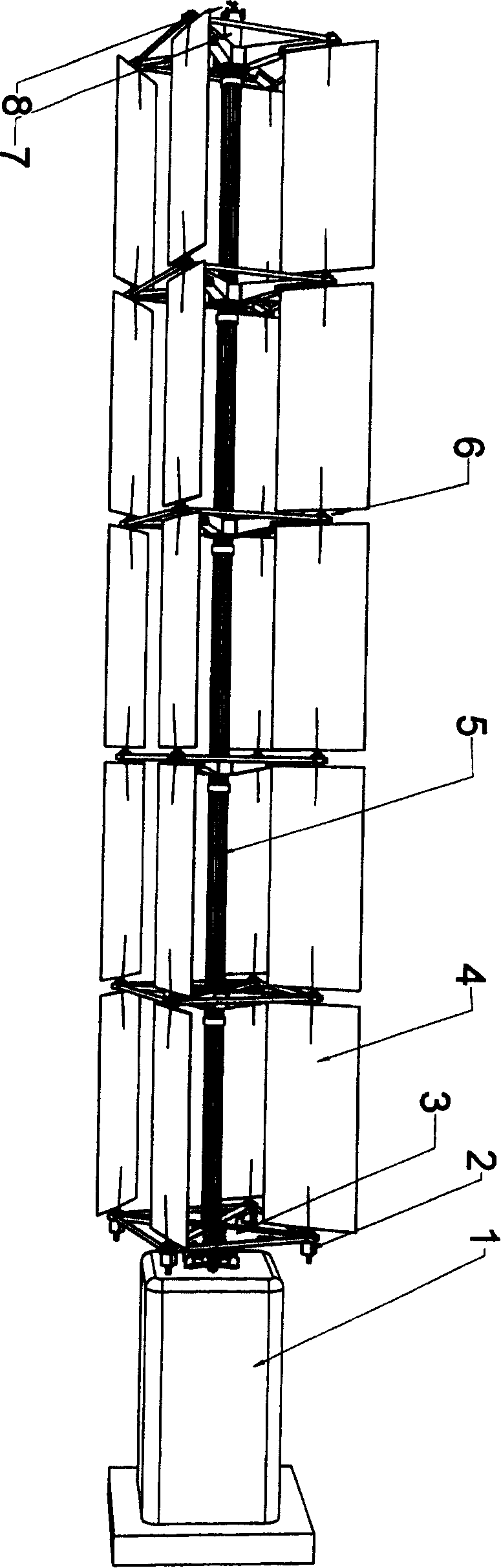
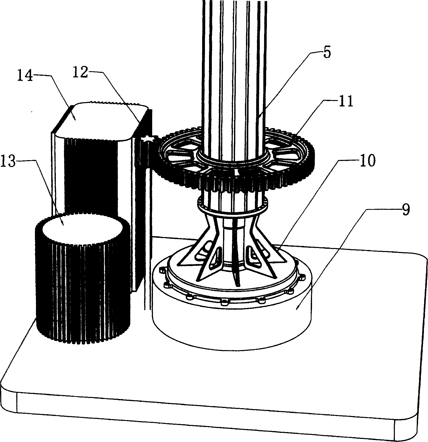
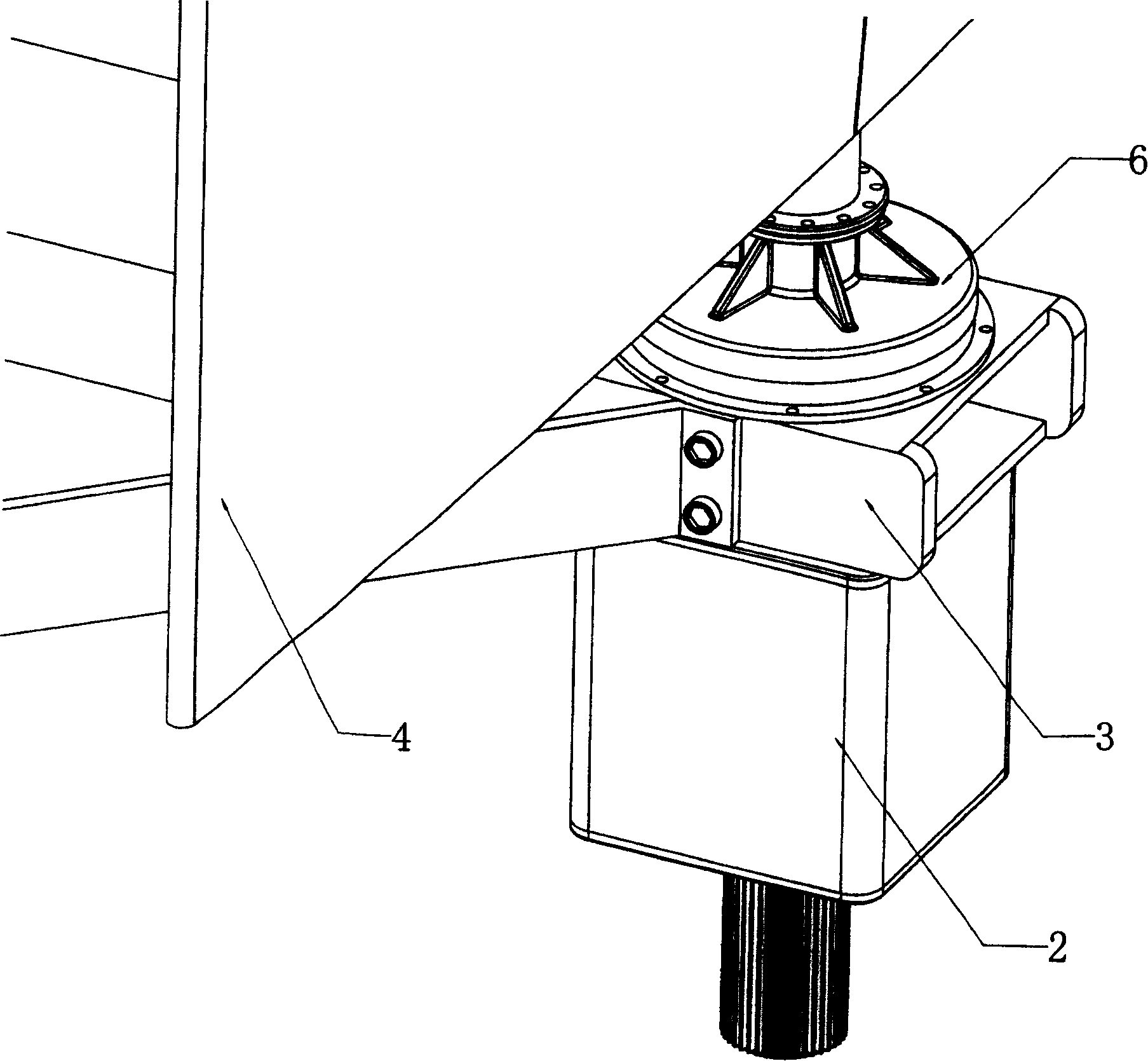
[0040] Such as Picture 1-1 , 1-2 , 1-3, 1-4, 1-5, the vertical axis wind power generator of the present invention is constituted like this: the whole is cylindrical, and there is a central column connected by central support column 5 in the center, and its There are multi-layered sail support discs 3, and four couplings 6 that can rotate around their own vertical axes are arranged on the edge of the sail support disc 3. The coupling 6 is a composite thrust bearing structure, and the thrust of the couplings 6 The installation hole A603 on the chassis 601 under the bearing is installed together with the sail blade support plate 3, and then the coupling 6 and the segmented sail blades 4 are connected through a flange to form a coaxial and same direction composite sail blade, specifically : the top of the coupling 6 is connected t...

Embodiment 2

[0056] The difference from Embodiment 1 is that as shown in Figures 1-6, an outer ring 16 is set on the outer wall of the central support column 5 at the top of the generator room 1, and a plurality of idlers 17 are installed on the top of the generator room, and are connected with the outer ring 16. The ring 16 abuts to strengthen the stability of the central support column 5 in motion. The front view of the idler 17 is shown in Figure 1-6-1, and the top view is shown in Figure 1-6-2.

[0057] The present invention can directly fix the permanent magnet material 15 on the upper and lower chassis of the shaft coupling thrust bearing and the main thrust bearing.


PUM


Abstract

The invention is a layer-assembled structure, in which a composite blade is made up of a blade and an integral central column assembled by a central support column and a blade support disk via a shaft coupling. The bottom of the central column is mounted on the base via a main bearing connected with the generator through a drive mechanism. The top of the central column is anchored via a cable fixator and a wind vane is disposed above the cable fixator. The sensor on the wind vane is connected with the composite blade via a control system.

Description

technical field [0001] The invention relates to wind power generation technology, in particular to a vertical-axis high-power wind power generator equipped with segmented sail blades and composite thrust bearings, which can control the best windward angle of sail blades. Background technique [0002] At present, most of the wind power generators in operation in the world are horizontal axis wind power generators. Although they are widely used, there are still some structural problems. First of all, the paddle wheel of the horizontal axis wind turbine acts on the top of the supporting tower, making the supporting tower a cantilever beam structure (all the blades of the blades are cantilever beams). When using this structure to manufacture high-power wind turbines, the tower height is average In order to maintain the stability of such a high support tower, the tower body structure is required to be very strong and have a high-strength concrete foundation on the ground, so as t...

Claims


Application Information

Patent Timeline
Patent Type & Authority Patents(China)
IPC IPC(8): F03D7/06F03D11/00F03D9/00F03D9/25F03D80/70
CPCY02E10/723Y02E10/722Y02E10/72Y02E10/74
Inventor 曾碚凯罗伯特·布丁大卫·布斯曼
Owner 曾碚凯
Why Eureka
Try Eureka