Separated two pbase flow liquid level controller

A liquid level controller, a split-type technology, applied in liquid level control, non-electric variable control, control/regulation systems, etc., can solve the problem of the cumbersome structure of the liquid level controller, the inflexibility and convenience of system connection, maintenance and layout, etc. problems, to achieve the effect of easy installation, layout and maintenance, good adjustment performance and simple structure

Inactive Publication Date: 2008-05-07
XI AN JIAOTONG UNIV
View PDF6 Cites 0 Cited by
  • Summary
  • Abstract
  • Description
  • Claims
  • Application Information

AI Technical Summary

Problems solved by technology

[0003] The above-mentioned patent has many significant advantages, so it is widely used in industry, such as "vapor-liquid two-phase flow liquid level controller", but the liquid level controller is still cumbersome in structure; it is not enough in system connection, maintenance and layout. flexible and convenient

Method used


Image

  • Separated two pbase flow liquid level controller
  • Separated two pbase flow liquid level controller
  • Separated two pbase flow liquid level controller

Examples


Embodiment Construction

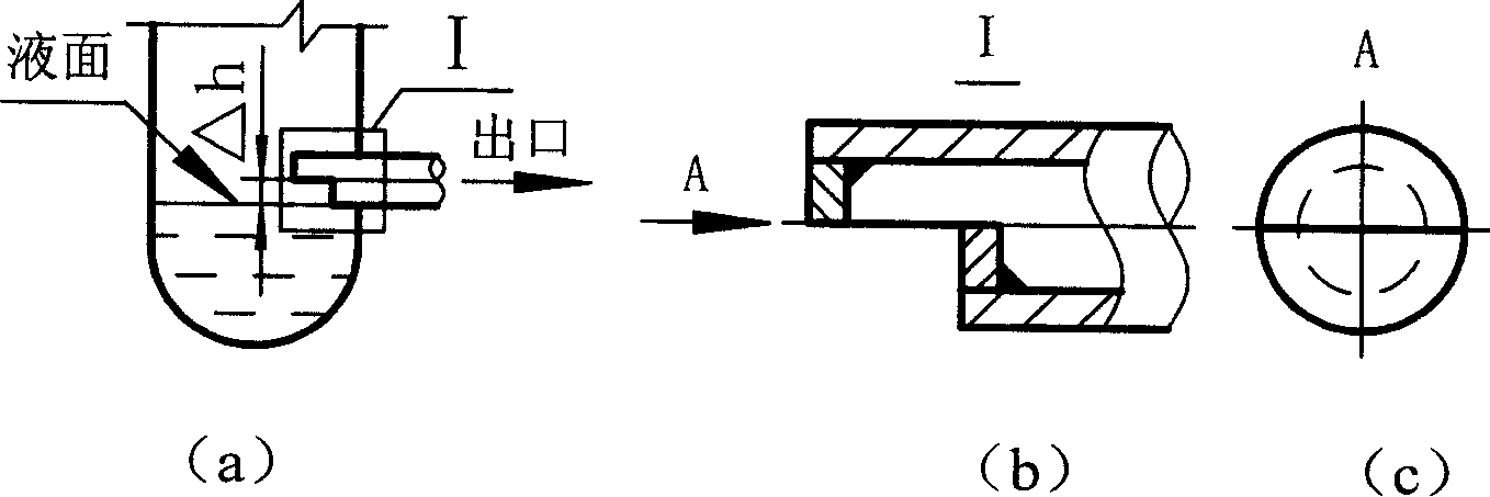
[0018] The structure of the split two-phase flow controller is as follows: figure 1 shown. It consists of industrial container (liquid level control object) 1, steam flow transmitter 2, throttling and pressure reducing element 3, two-phase flow controller 4, tee 8, three gate valves 5, 7, 9 and other equipment. The specific connection is described as follows. The drain pipe 12 at the bottom of the industrial container 1 is connected to the first gate valve 9, and the first gate valve 9 is connected to the throttling and pressure-reducing element 3. The controller 4 is connected to the pipeline leading out from the steam flow transmitter 2, and the two-phase flow controller 4 is connected to the second gate valve 5 and the outlet pipe 6 behind. A bypass pipe 10 is connected between the discharge pipe 12 at the bottom of the industrial container 1 and the outlet pipe 6 behind the gate valve 5, and the third gate valve 7 is connected in the pipe.

[0019] Its liquid level adjus...


PUM


Abstract

The present invention disclosed a split type two-phase fluid level controller. It is composed of industrial container, steam flow transmitter, throttling pressure-reducing element and two-phase fluid controller. Said invention utilizes the flowing characteristics of steam and liquor two-phase fluid to change the capability for outputting liquor so as to attain the goal of controlling level.

Description

technical field [0001] The invention belongs to the technical field of automatic control, relates to a method for controlling the liquid level inside a container, in particular to a split-type two-phase flow liquid level controller. Background technique [0002] Liquid level controllers are widely used equipment in industrial production. At present, the liquid level regulators widely used in industry are mechanical, pneumatic and electric. They all realize the automatic adjustment and control of the liquid level through external mechanical, electrical or pneumatic devices. These regulators are often jammed and other failures due to frequent actions, easy wear and corrosion of the actuators, or the liquid level is out of control due to failures such as electrical, pneumatic components and lines, which seriously affect the safe and economical operation of equipment and systems; Processes, quality and quantity of products. There is an urgent need to invent a more novel, more ...

Claims


Application Information

Patent Timeline
Patent Type & Authority Patents(China)
IPC IPC(8): G05D9/00G05D9/02
Inventor 林万超陈国慧邢秦安
Owner XI AN JIAOTONG UNIV
Why Eureka
Try Eureka