Ray projection method and device of optical mouse

A technology of an optical mouse and a projection device is applied in the field of light projection method and device of an optical mouse, and can solve the problems of insufficient contrast between light and dark, increased detection difficulty by an image detection element 4, and difficulty in controlling cursor movement.

Inactive Publication Date: 2008-04-02
PACING TECH
View PDF5 Cites 0 Cited by
  • Summary
  • Abstract
  • Description
  • Claims
  • Application Information

AI Technical Summary

Problems solved by technology

However, the image detection surface 5 is a concave-convex surface. When the light beam L is vertically projected onto the image detection surface 5, the light-dark contrast between the concave and convex portions of the image detection surface 5 is not obvious enough, resulting in The detection difficulty of the image detection element 4 is increased
As a result, when the optical mouse is moved on the image detection surface 5, the movement of the cursor on the display screen is not sensitive enough, especially when the optical mouse is moved at a high speed, it is more difficult to control the movement of the cursor
[0007] It can be seen from the above that the above-mentioned known optical mouse light projection method and device obviously have inconvenience and defects in actual use, and need to be improved.

Method used


Image

  • Ray projection method and device of optical mouse
  • Ray projection method and device of optical mouse
  • Ray projection method and device of optical mouse

Examples


Embodiment Construction

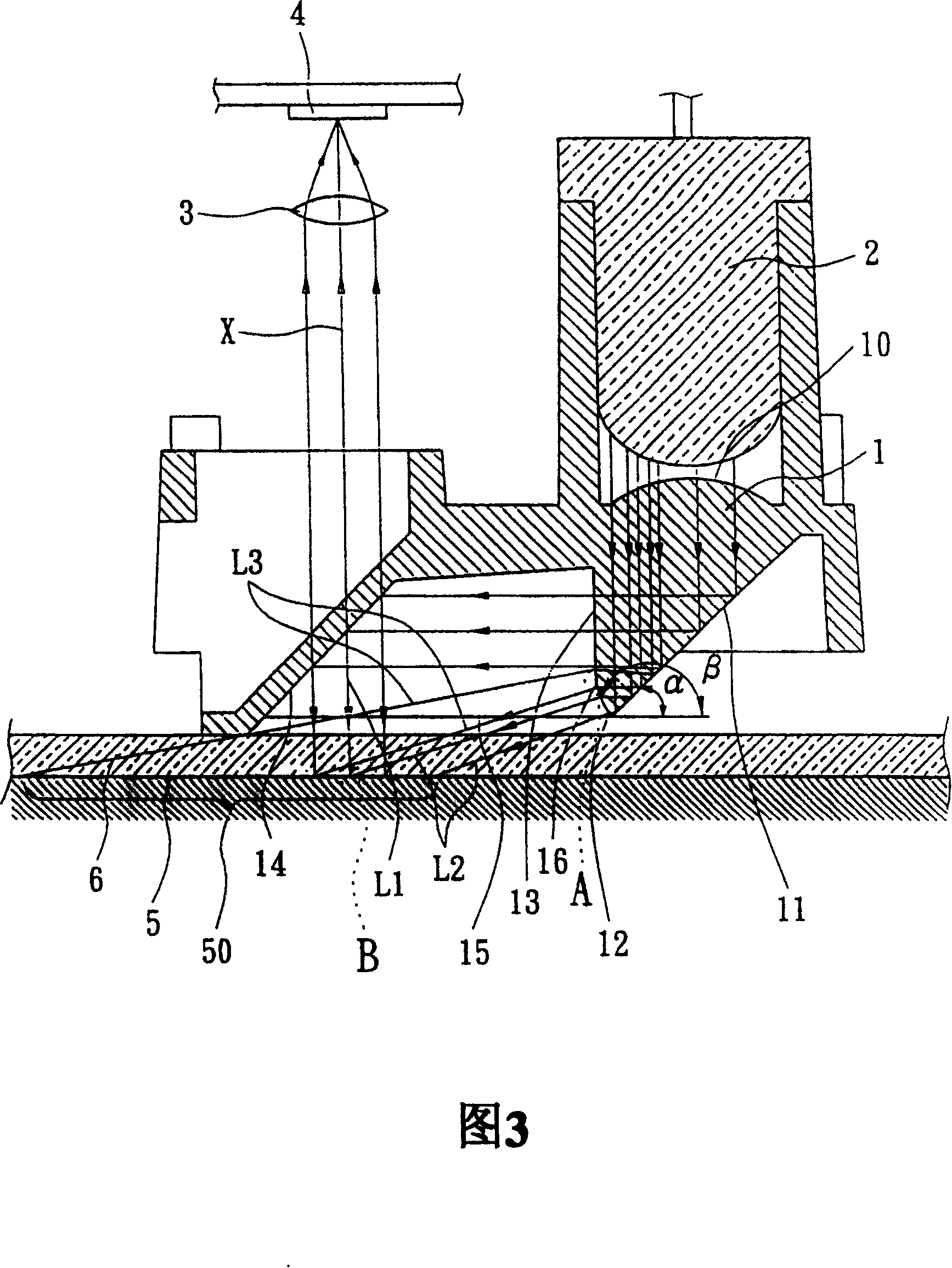
[0062] For further elaborating the technical means and effects that the present invention takes to achieve the intended purpose, please refer to the following detailed description and accompanying drawings of the present invention. It is understood that the accompanying drawings are only for reference and illustration, and are not intended to limit the present invention.

[0063] Please refer to FIG. 3 , which is the first embodiment of the present invention. The invention relates to a light projection method and device for an optical mouse. The optical mouse includes a light projection device 1 , a light source 2 , an imaging lens 3 , an image detection element 4 and the like.

[0064] The steps of the light projection method of the optical mouse of the present invention comprise:

[0065] (1) providing a light projection device 1;

[0066] The light projection device 1 of the optical mouse of the present invention includes a light guide body, and the imaging lens 3 can be...


PUM


Abstract

A light projection method of optical mouse includes providing a light projection unit, entering projection light into light projection unit for forming the first light beam and the second light beam, projecting the first light beam to detection region of an image detection surface for picking up image on said detection region accurately, projecting the second light beam to said detection region obliquely to make bright - black contrast of convex and concave position on detection region more obvious for raising identification ability of image detection unit on detection region.

Description

technical field [0001] A light projection method and device, especially a light projection method and device for an optical mouse. Background technique [0002] When the optical mouse is moved on an image detection surface, the optical mouse detects the images of the recesses and protrusions on the image detection surface through its image detection element, and further performs energy level adjustment through its circuit unit. transformation, to calculate the displacement direction and displacement amount of the optical mouse, so that it can move a cursor on a display screen. [0003] Please refer to FIG. 1 , which is a known optical mouse, which includes a light projection device 8 , a light source 2 , an imaging lens 3 , and an image detection element 4 . The light projecting device 8 includes a light guide body having a convex lens surface 80 , a first inclined surface 81 , a second inclined surface 82 , and a light emitting surface 83 . The first slope 81 corresponds ...

Claims


Application Information

Patent Timeline
Patent Type & Authority Patents(China)
IPC IPC(8): G06F3/033G06F3/0354
Inventor 吕淑芬
Owner PACING TECH
Why Eureka
Try Eureka