Self controlling location seeding mechine

The technology of a seeder and a seeding device is applied in the direction of interval quantitative seeding machinery, fertilizer and seeding equipment, agricultural machinery and equipment, etc. It can solve the problems of inconsistent width of furrows, insufficient film spreading, uneven seeds, etc., and achieve the best seeding depth. Consistent, conducive to water absorption, uniform seeding effect

Inactive Publication Date: 2008-04-02
臧均
View PDF8 Cites 0 Cited by
  • Summary
  • Abstract
  • Description
  • Claims
  • Application Information

AI Technical Summary

Problems solved by technology

[0002] At present, the existing seeders mainly have the following defects: 1. The positioning point of the sowing depth of the existing seeders is on the ground, and the land needs to meet the mechanical sowing conditions, rather than the machinery to adapt to different lands
During use, the contact point between the driving wheel and the ground keeps rising and falling, and the sown seeds will be deep and shallow, resulting in uneven emergence, long emergence time and low emergence rate, resulting in reduced crop yields
2. The two driving wheels of the existing seeder are positioned on the ground, load-bearing and drive the seeder to work, and sow seeds in the same field. The driving wheel is raised, and the sowing basket feet, fertilization basket feet, and ridge plows installed before and after the sowing wheel are raised accordingly, and the sown seeds are shallow, or even completely exposed on the ridge surface; when the driving wheel moves When the soil is soft, the soil is fine, the soil is loose, the moisture is waterlogged, or the ground is concave, the driving wheel will sink immediately, and the basket legs, plows and other parts will also be tied down, and the seeds sown will be deep, even as deep as 100mm. At the same time, the front of the cover plate is full of mud, so the tractor can't pull it, the driving wheel slips, the seeds are not evenly sown, the crop seedlings are uneven, the seedlings are weak, and the yield is reduced.
Because the two driving wheels are installed at both ends of the same shaft, they travel across the ridges and have synchronization, and can only run straight or approximately straight. When planting on a curved hillside, the tractor turns and the planter cannot turn. Forced pulling and dragging will cause lateral movement when moving forward, so the width of the furrows is inconsistent, wasting land
The planter cannot work in the sprinkler irrigation field, the ground of the sprinkler irrigation field cannot be level, the relative humidity of the convex place is low, the sown seeds will be shallow, and the relative humidity of the concave place is high, and the sowing will be deep
3. The ridge supported by the existing seeder is a low trapezoidal ridge with a narrow surface and a small lighting area
4. Existing planters use soil-covering boards to scrape the ridge surface, which has high resistance, and also causes uneven width and unevenness of the ridge surface, which affects the quality of the covering film. At the same time, the soil covering the seeds is loose, which is not conducive to water absorption, germination, rooting, and growth of the seeds.
5. The existing seeder adopts a row of fertilization in the middle of the ridge. The fertilization is shallow and concentrated, which makes it difficult for crops to absorb and rots easily.
6. The laminating device of the existing seeder is not coordinated with the film releasing rod and the laminating roller, the film is not fully developed, it is easy to wrinkle and tear the edge, the tension is not tight, the laying is not smooth, the pressure is not tight, and the ditch is still glued. When the wind is strong, the film is placed The mulching film on the film rod will automatically unfold, and it cannot be covered when it flutters with the wind. Every time a new ridge is covered, the film needs to be manually stretched and pressed to start work, which is time-consuming and laborious.
There are gaps between the hitch collar, the pin, and the hole of the traction plate. The gap between the hitch and the traction device is adjusted by rotating the bolt. This adjustment method is difficult to achieve the desired effect. Hold the handrail of the tractor, raise the planter to turn, and the planter does not swing left and right, then when the planter is put down to work, there will be no reasonable movable gap between the traction device and the hitch device, and the two cannot work together. If there is a reasonable working gap between the hitch devices, when the seeder is raised, the seeder will swing from side to side, which is easy to hurt the operator's legs, which is extremely unsafe. Correcting the position of the planter to keep it in line with the tractor is time-consuming and labor-intensive

Method used


Image

  • Self controlling location seeding mechine
  • Self controlling location seeding mechine
  • Self controlling location seeding mechine

Examples


Embodiment

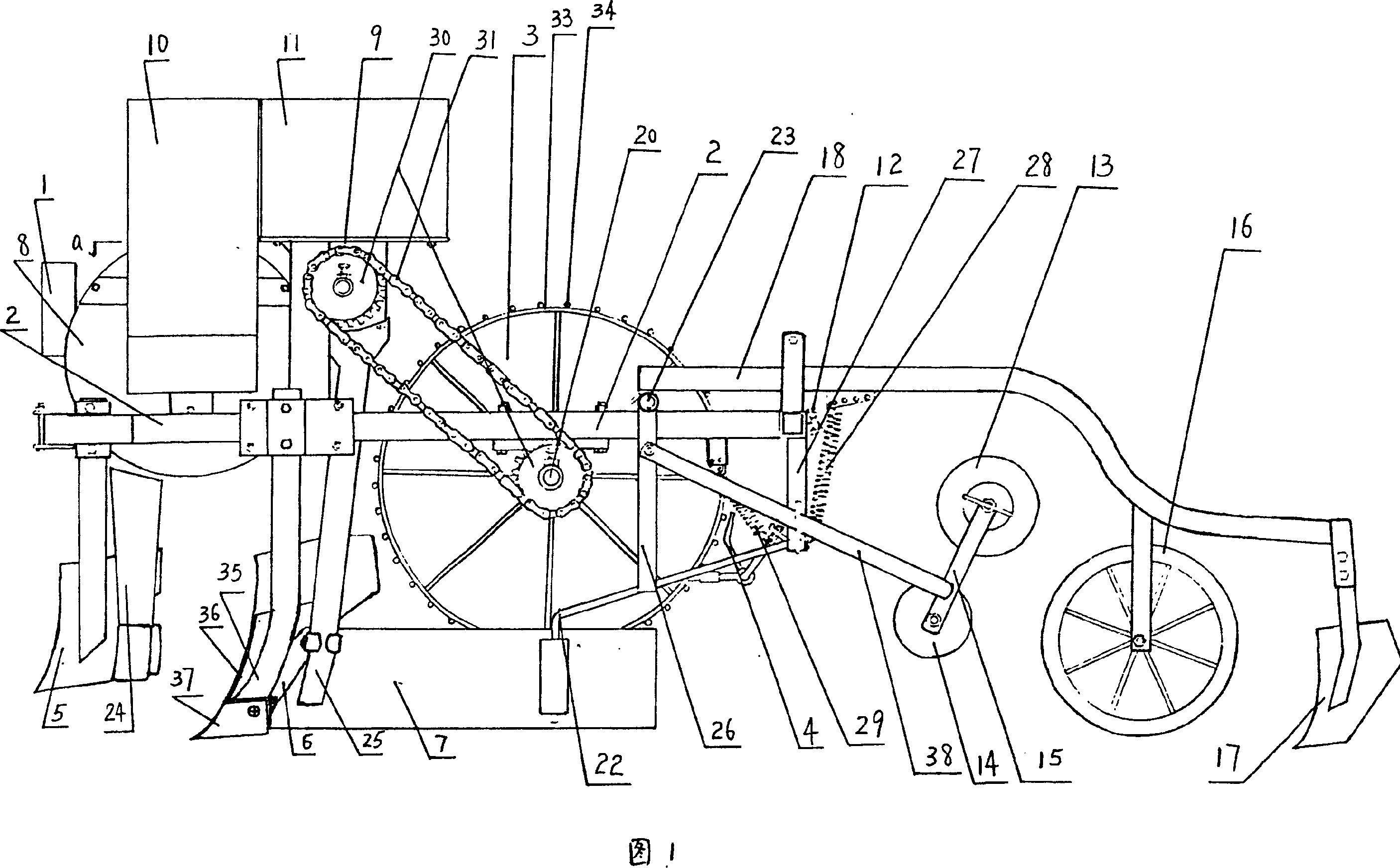
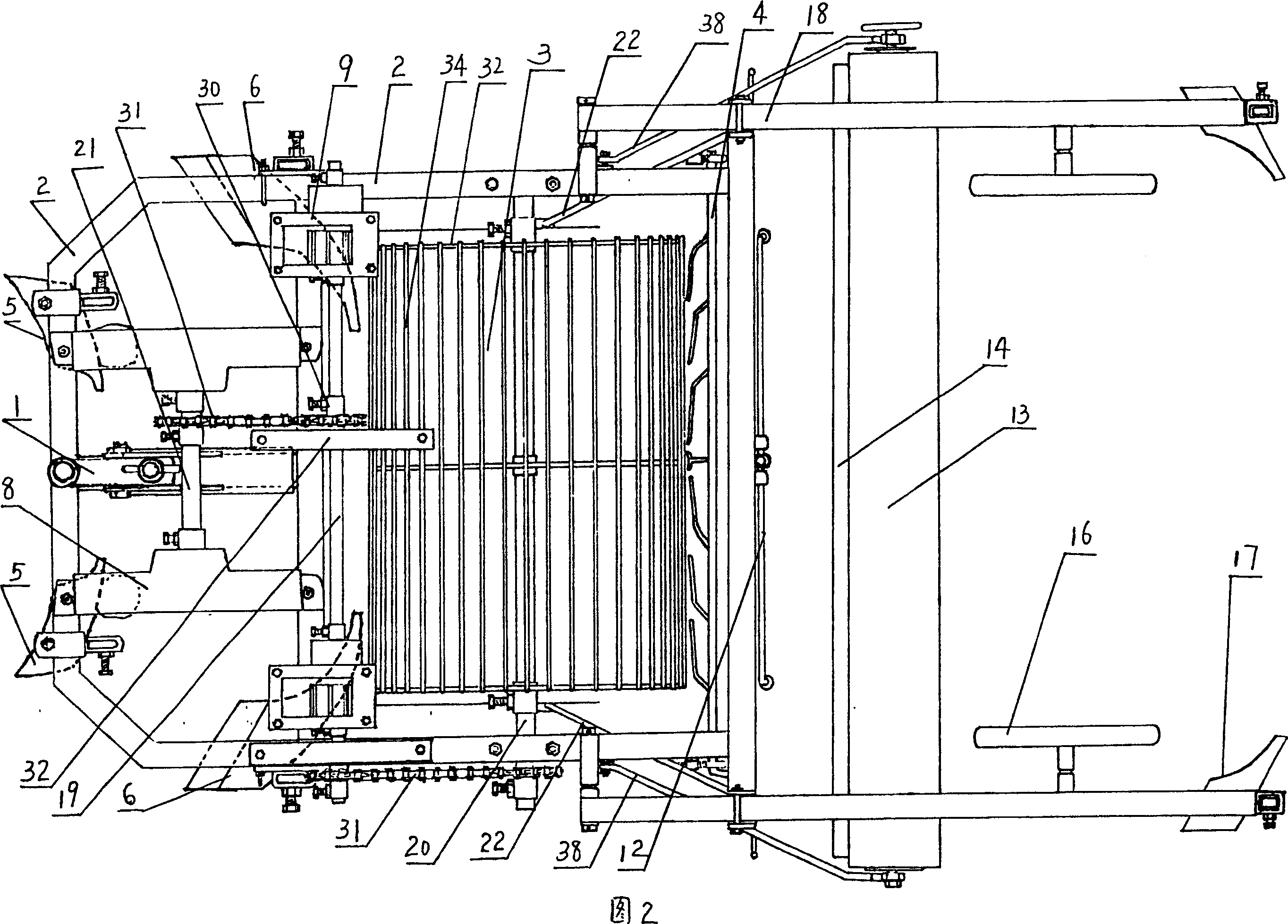
[0018]Embodiment: a kind of self-control positioning seeder (referring to Fig. 1-Fig. 4), it comprises frame 2, the front portion of frame 2 is provided with two pairs of plows, and front pair is two ridge-supporting sowing plows 5, is located at The two sides of the frame are symmetrical to each other, and the back pair is two ridge-supporting and fertilizing plows 6, which are symmetrical to each other on both sides of the frame. The ridge-supporting sowing plow 5 and the ridge-supporting fertilization plow 6 have the same structure, and both include a plow handle 35 and a plow wall 36, and the plow wall 36 connects to the plow point 37, and the plow point 37 is V-shaped (the ridge-supporting sowing plow 5 can also be a disc shaped plow). After each ridge fertilization plow 6 is connected with a plastic ridge plate 7, the outer side of the plastic ridge plate 7 blocks the plastic ridge plate 7 by the plastic ridge plate fixing frame 22 to avoid moving outwards, and the plast...


PUM


Abstract

A sower able to automatically control the sowing depth is composed of machine frame, sowing unit, fertilizer applying unit, plough, connecting unit, and the rotating unit connected behined the plough for driving said sowing unit and fertilizer applying unit.

Description

(1) Technical field: [0001] The invention relates to a self-control positioning seeder, which belongs to the field of agricultural seeding machinery. (two) background technology: [0002] At present, the existing seeders mainly have the following defects: 1. The positioning point of the sowing depth of the existing seeders is on the ground, and the land needs to meet the sowing conditions of the machinery, rather than the machinery to adapt to different lands. During use, the contact point between the drive wheel and the ground keeps rising and falling, so that the sown seeds are suddenly deep and shallow, resulting in uneven emergence, long emergence time and low emergence rate, resulting in crop yield reduction. 2. The two driving wheels of the existing seeder are positioned on the ground, load-bearing and drive the seeder to work, and sow seeds in the same field. The driving wheel is raised, and the sowing basket feet, fertilization basket feet, and ridge plows installed...

Claims


Application Information

Patent Timeline
Patent Type & Authority Patents(China)
IPC IPC(8): A01C7/06A01C7/18
CPCY02P60/14
Inventor 臧均
Owner 臧均
Why Eureka
Try Eureka