Composite power system of outer jointed auxiliary power

A technology of auxiliary power and power system, which is applied in the field of mechanical power system, can solve the problems of power transmission partition, volume expansion, unsmooth connection, etc., and achieve the effect of simplifying structure, reducing cost and reducing cost

Inactive Publication Date: 2008-03-26
IND TECH RES INST
View PDF3 Cites 0 Cited by
  • Summary
  • Abstract
  • Description
  • Claims
  • Application Information

AI Technical Summary

Problems solved by technology

Therefore make electric motor and internal combustion engine must be arranged on the power take-off shaft in series, and make the volume of device expand
Moreover, since the power of the motor directly drives the drive shaft without being amplified, in order for the motor to have a large enough torque to drive the vehicle, its volume is relatively large
[0005] In addition, some hybrid power systems are provided with a driving mechanism for connecting the two power units between the electric motor and the internal combustion engine. However, the structures of these driving mechanisms are quite complicated, or they cannot achieve good results.
[0006] There are also some patents for hybrid power systems, which use the engine power and electric motor power as the power input of the sun gear and satellite gear of the planetary gear system, and use the relative connection of the wheel hub with the ring gear as the power output. This kind of power connection method, Since the engine power does not have a torque converter or similar torque transmission mechanism, when the engine speed changes greatly or the speed is unstable, the two powers cannot be smoothly connected, and when the engine is idle, the power transmission cannot be cut off, so Such institutions are not practical

Method used


Image

  • Composite power system of outer jointed auxiliary power
  • Composite power system of outer jointed auxiliary power

Examples


Embodiment Construction

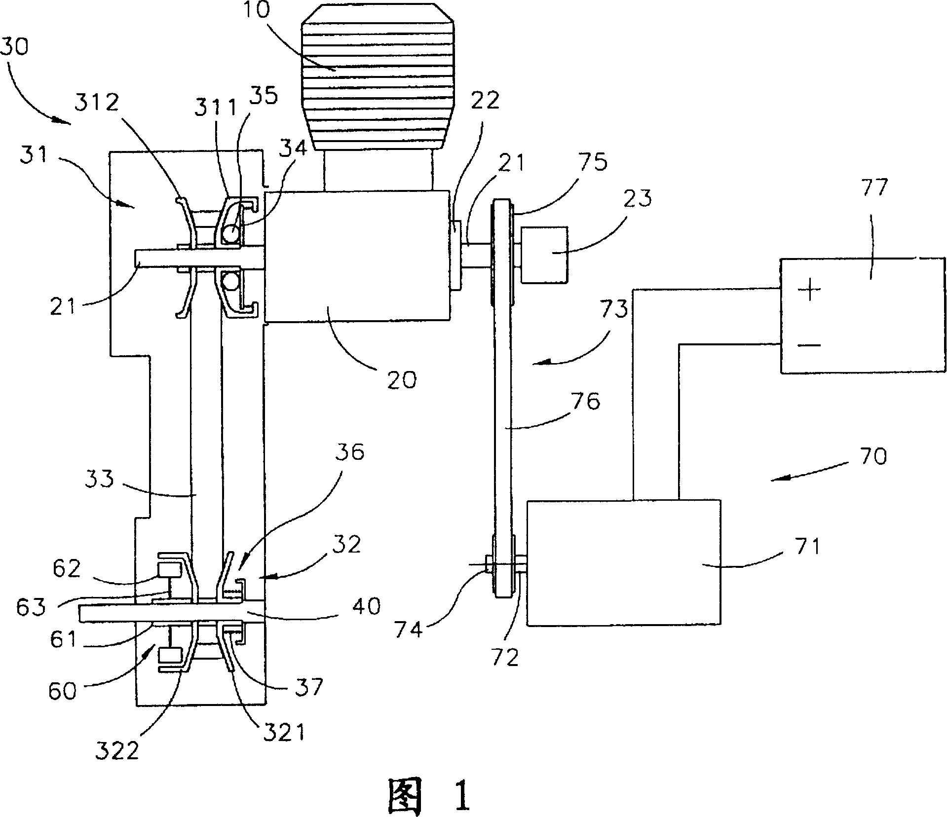
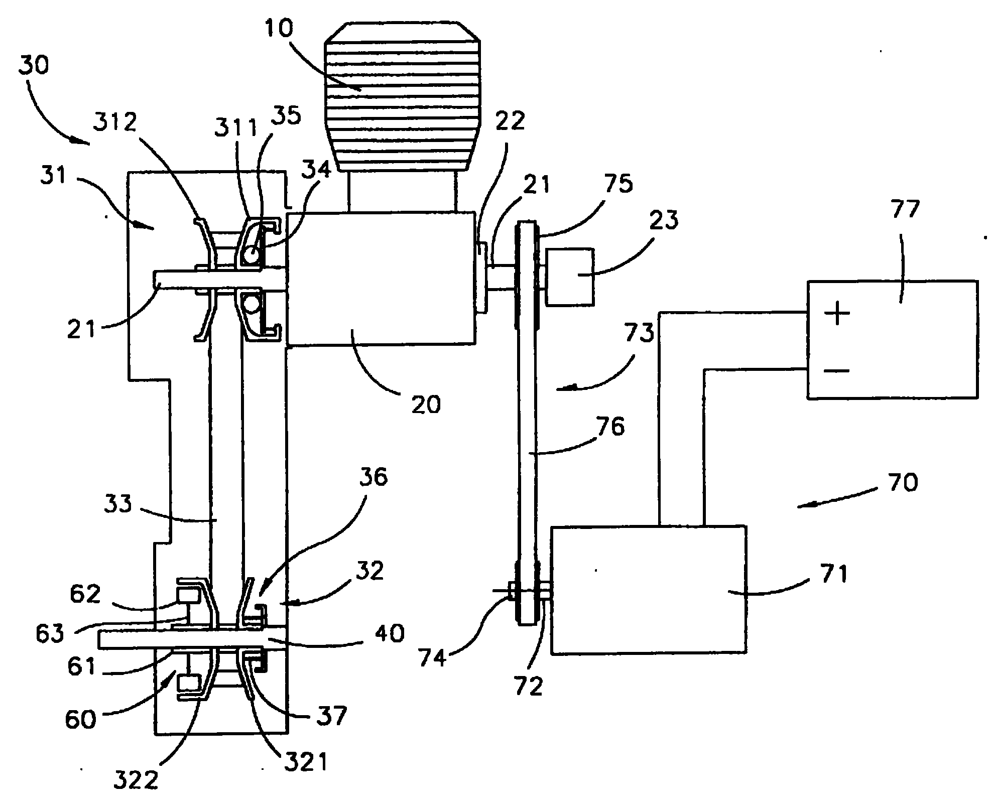
[0056] As shown in Figure 1, the present invention mainly includes: a first power unit 10, a transmission box 20, a first transmission mechanism 30, an output shaft 40; and an auxiliary power unit 70 and a second transmission mechanism 73; wherein the first The power of the power unit 10 can drive the first drive shaft 21 to rotate through the inside of the transmission box 20; the first drive shaft 21 is connected to the first transmission mechanism 30, and can drive the output shaft 40 through the first transmission mechanism 30 Rotate, and then output power through the output shaft 40 to drive the driving wheels of the vehicle, so that the vehicle moves forward.

[0057] The first power unit 10 can be any type of power unit, and the embodiment shown in the figures is an internal combustion engine. The transmission box 20 can be a crankshaft mechanism. The first power unit 10 drives the first drive shaft 21 to rotate through the crankshaft and reduction gear set (not shown),...


PUM


Abstract

A combined power system with externally connected auxiliary power is composed of a first power unit (miniature IC) engine) consisting of a first power equipment, a first drive shaft, an output shaft and a first driver between the first driven shaft and the output shaft, an auxiliary power unit consisting of a motor and its drive shaft parallel to the first driven shaft, and a second driver connected between the first and the second drive shafts.

Description

technical field [0001] The invention belongs to a mechanical power system, in particular to a composite power system. Background technique [0002] Traditional vehicles use an internal combustion engine as the power source, and the power is transmitted to the wheels through the transmission box to drive the vehicle forward. Since the internal combustion engine uses fuel to generate power, it will produce toxic exhaust gas to pollute the air. For the purpose of environmental protection, electric vehicles have been invented. This type of vehicle no longer uses internal combustion engines as power, but uses batteries combined with electric motors as the power source. , that is, the electric power of the battery is converted by the electric motor to generate mechanical power, and then the wheels are driven through the transmission box. However, electric vehicles are limited by the insufficient power energy that batteries can store, making the driving distance of electric vehicl...

Claims


Application Information

Patent Timeline
Patent Type & Authority Patents(China)
IPC IPC(8): B60K6/00B62M23/02B60K6/22B60K6/36
Inventor 古焕隆巫金台解潘祥李文彬吕俊贤
Owner IND TECH RES INST
Why Eureka
Try Eureka