


Quick Research
Generate reliable direction feasibility study reports for your R&D in just a few steps.

Technical Q&A
Discover and master advanced knowledge NOW. Basics, ideas, possibilities, all at once.

Find Solutions
As an expert in R&D theories, this can generate solutions to your technical problems instantly.

Evaluate Feasibility
Analyze your overall solution with one click, know your potential R&D risks in advance.

Monitor Landscape
Get weekly tech updates, stay abreast of the latest tech innovations and key insights.
Displacement speed sensor and off-table type mouse
A speed sensor and displacement technology, applied in the direction of instruments, electrical digital data processing, input/output process of data processing, etc., can solve the problems of "mouse hand" easily caused, not widely used, poor complete set, etc., to achieve complete set Good, easy to operate, wide application effect
- Summary
- Abstract
- Description
- Claims
- Application Information
AI Technical Summary
Problems solved by technology
Method used
Image

Examples
Embodiment 1
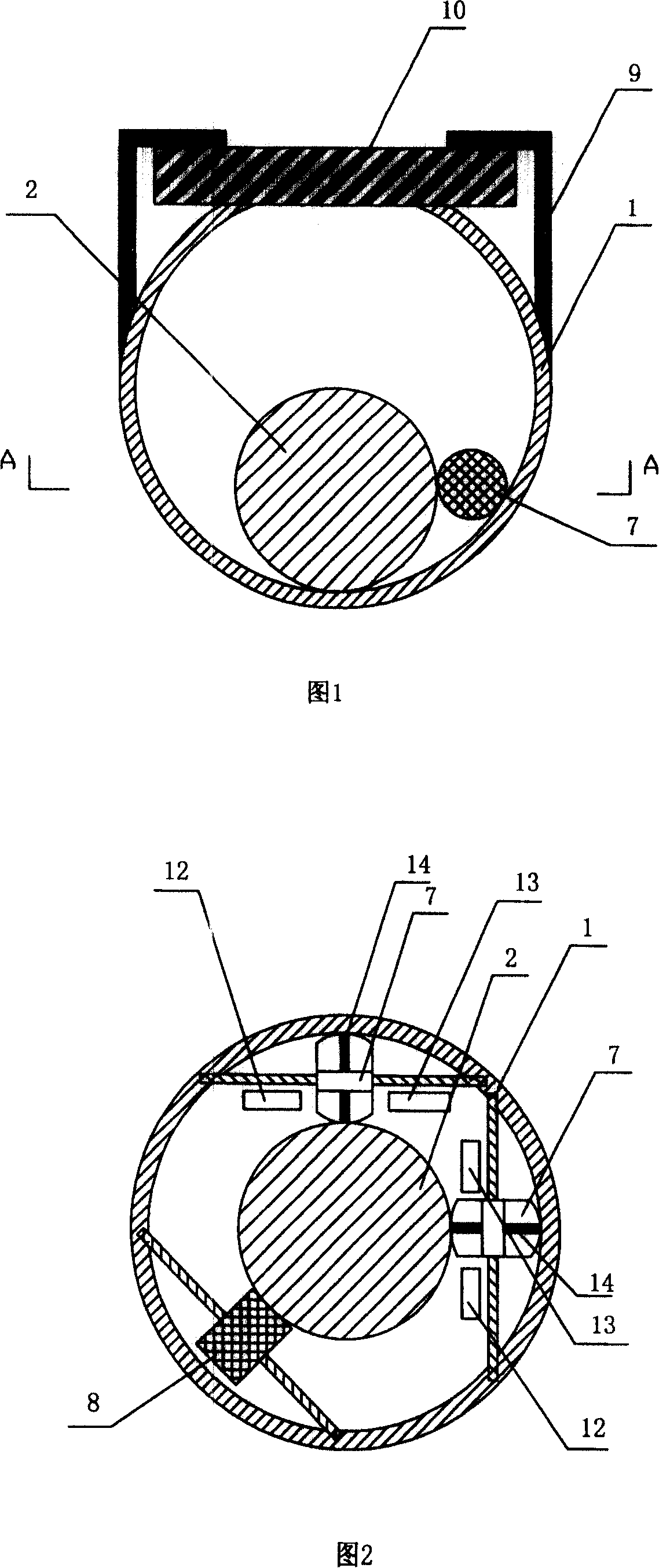
[0045] Embodiment 1: Displacement velocity sensor, comprises optical signal transmitter 12, optical signal receiver 13 and displacement velocity sensor, and displacement velocity sensor comprises arc surface shell 1, the inertia positioning ball 2 in arc surface shell 1. In this embodiment, the optical signal transmitter 12 is an infrared emitting tube, and the optical signal receiver 13 is an infrared receiving tube. Inertial positioning ball 2 is a eccentric ball, and the center of gravity is located on the central axis below its center of sphere. The curved shell 1 is spherical. As shown in Fig. 1 and Fig. 2, the displacement speed sensor also includes around the inertial positioning ball 2, two roller grating wheels 7 and a pinch wheel 8 at right angles to each other, which are fixed on the inner spherical surface of the arc surface shell 1, and the pinch wheel 8 The angle between the two roller grid wheels 7 is in the opposite direction, and they are on the same plane, s...
Embodiment 2
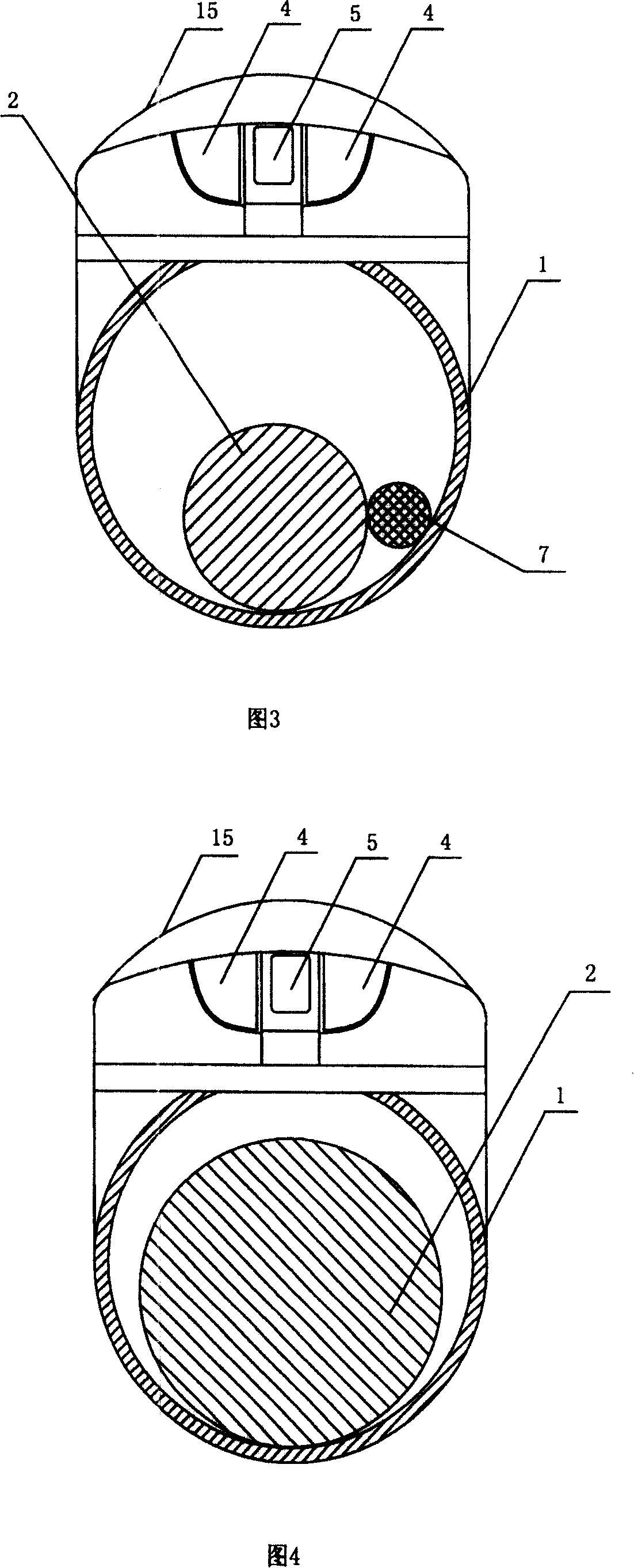
[0048] Embodiment 2: As shown in Figure 3, the off-desk mouse is improved on the basis of the existing semi-optical mechanical mouse. The structures of the two soft-touch buttons 4 and the scroll wheel 5 between the two are the same as those of the existing semi-opto-mechanical mouse. The difference is that the rolling ball originally placed in the cavity at the bottom of the mouse plane is changed to an inertial positioning ball 2, and the plane bottom of the original mouse extends downwards and is fixedly connected with the arc surface shell 1 (the arc surface shell 1 in this example is spherical) . The inertia positioning ball 2 in this embodiment is also an eccentric ball, and its spherical surface and the inner spherical surface of the curved shell 1 are smooth surfaces. The center of gravity of the inertia positioning ball 2 is located on the central axis below its center of sphere. Around the inner spherical surface of the arc surface shell 1 and the inertia positioni...
Embodiment 3
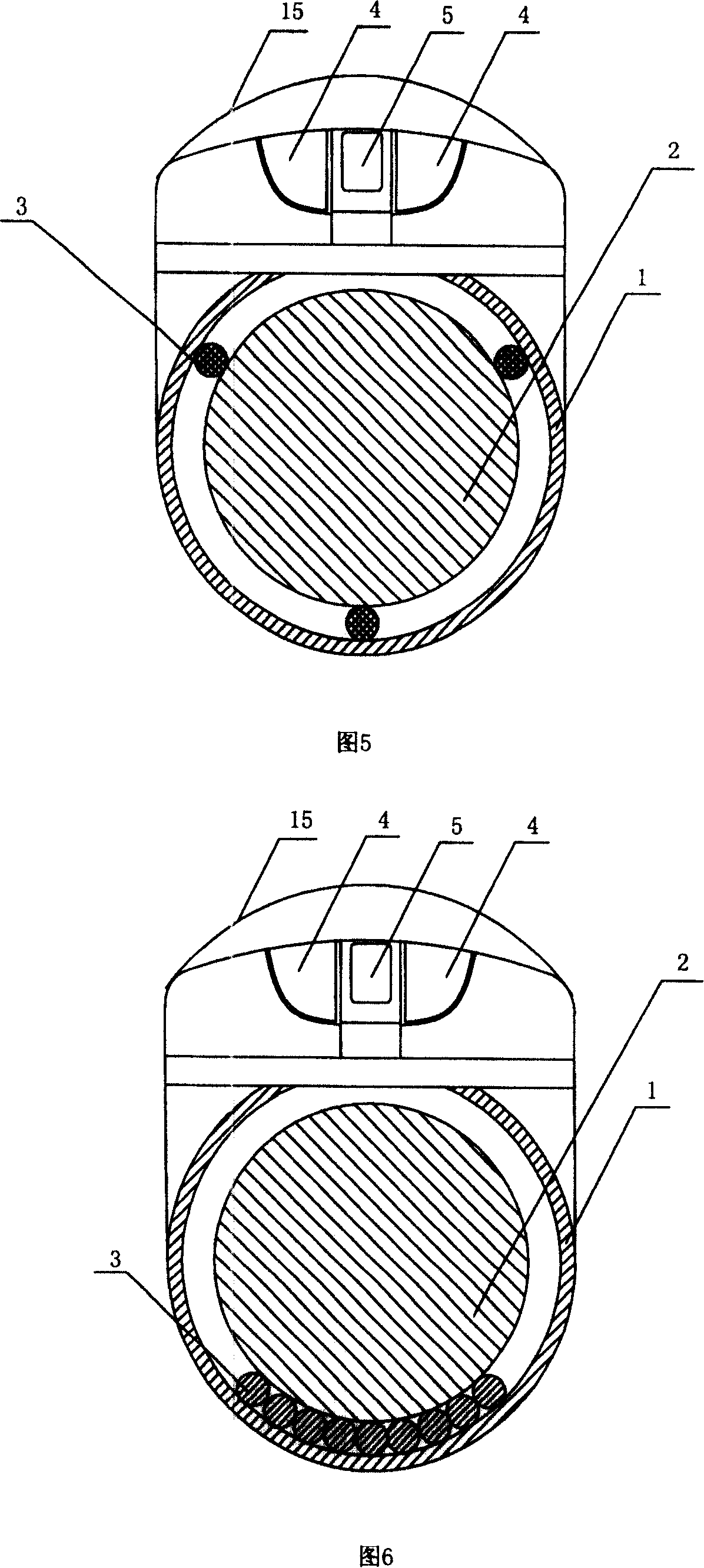
[0051] Embodiment 3: As shown in Figure 4, the off-desk mouse is improved from the photoelectric mouse. Optical signal transmitter 12, optical signal receiver 13, microprocessor, light touch button 4, scroll wheel 5 etc. are all arranged in the common photoelectric mouse of top. Its displacement speed sensor is made of arc surface shell 1 (spherical), inertia positioning ball 2. The inertia positioning ball 2 is provided with a gyroscope inside, and the inertia positioning ball 2 "automatically" returns to the initial state after rolling by relying on its self-stabilizing balance, so as to realize the relative displacement and speed with the arc surface shell 1. An opening is arranged at the upper end of the arc surface shell 1, and the inertia positioning ball 2 is built in the arc surface shell 1, and the arc surface shell 1 is fixedly connected with the shell of an ordinary photoelectric mouse. The inner spherical surface of the arc surface shell 1 and the spherical surfac...
PUM
 Abstract
Description
Claims
Application Information
 - R&D Engineer
- R&D Manager
- IP Professional
- Industry Leading Data Capabilities
- Powerful AI technology
- Patent DNA Extraction
Browse by: Latest US Patents, China's latest patents, Technical Efficacy Thesaurus, Application Domain, Technology Topic, Popular Technical Reports.
© 2024 PatSnap. All rights reserved.Legal|Privacy policy|Modern Slavery Act Transparency Statement|Sitemap|About US| Contact US: help@patsnap.com