Air conditioner

An air conditioner, air technology for use in the direction of air conditioning systems, space heating and ventilation, space heating and ventilation details

Inactive Publication Date: 2008-03-05
HITACHI APPLIANCES INC
View PDF6 Cites 0 Cited by
  • Summary
  • Abstract
  • Description
  • Claims
  • Application Information

AI Technical Summary

Problems solved by technology

[0010] The task of the present invention is to solve the problem that the parts inside the indoor unit can be replaced from the outside of the wall where the indoor unit is installed, and maintenance such as cleaning can be performed.

Method used


Image

  • Air conditioner
  • Air conditioner
  • Air conditioner

Examples


Embodiment Construction

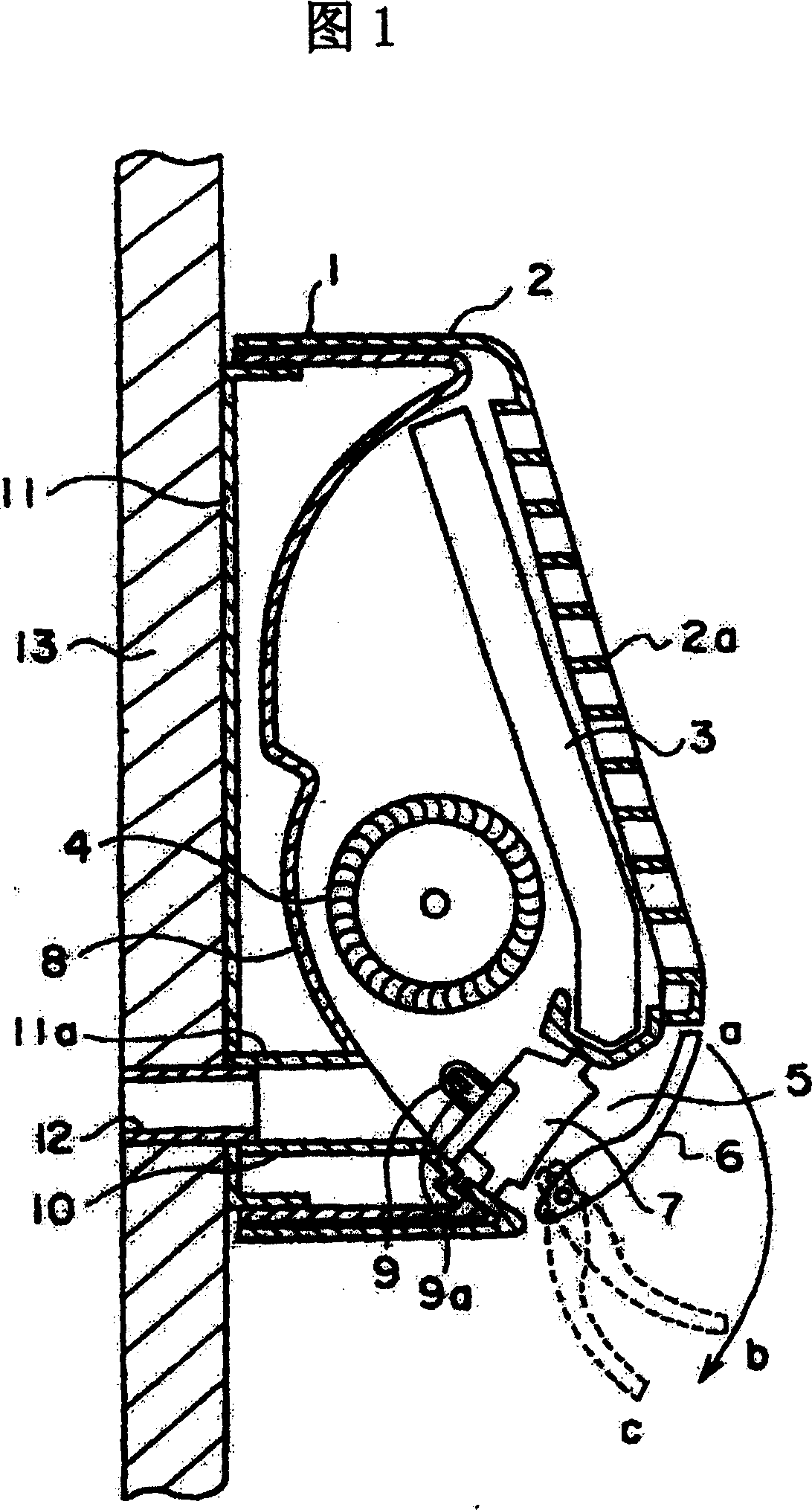
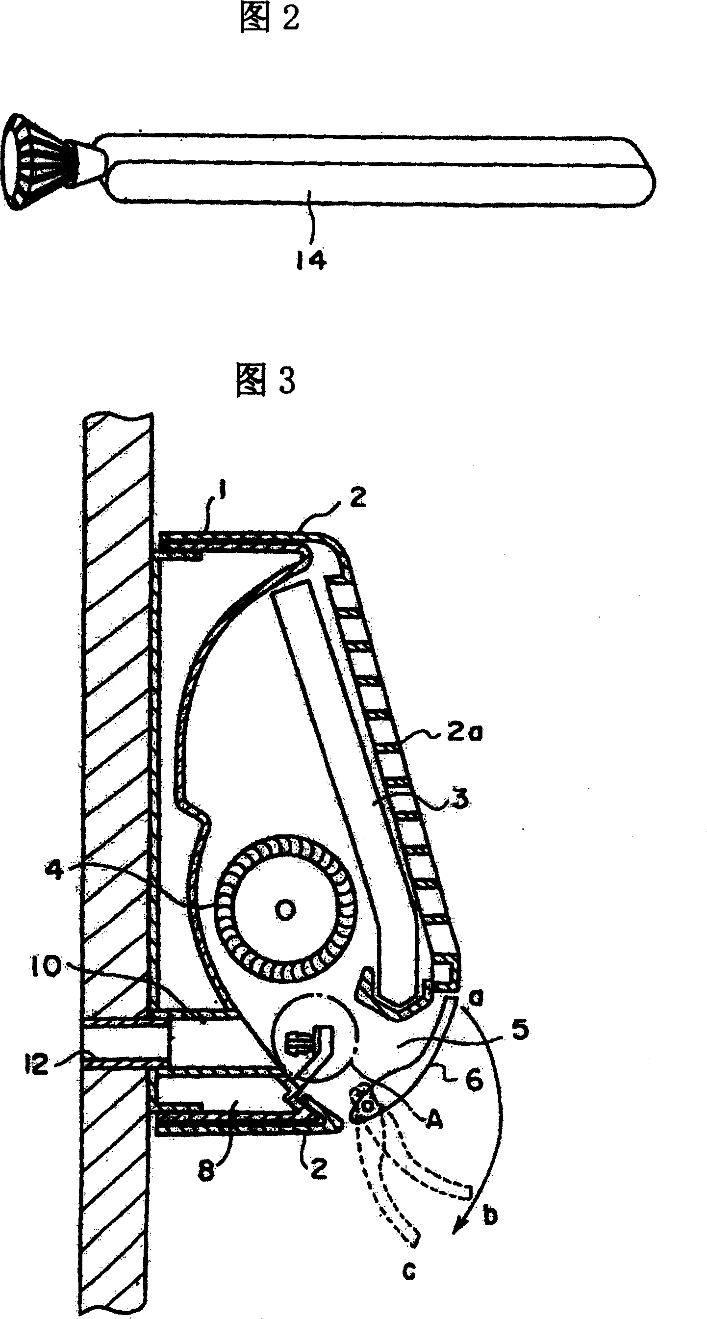
[0033] Fig. 1 is the general structure of the embodiment of the present invention, formed opening part (pipeline 10) at the back side of indoor unit, so that can carry out various inspection and maintenance to the indoor unit 1 of air conditioner at any time from the outside, through above-mentioned opening part (10) With the through hole (pipe 12) formed on the wall where the indoor unit is installed, replacement of parts, cleaning of the indoor unit, and installation of components for adding substances that have an effect on the discharged air can be performed.

[0034] Next, it is mainly for the maintenance of the negative oxygen ion generator (Figure 1) installed inside the indoor unit, and the replacement and cleaning of the filter (Figure 10) installed in the indoor unit, or for the through holes on the wall and indoor The structure of the opening part on the back of the machine will be described, but the present invention is not limited to these points, it can be applied...


PUM


Abstract

Holes (duct 10 for service and in-wall duct 12) penetrated through a back plate 11 of the indoor machine 1, an installed member and an installation wall 13, are formed and the components 9a inside of the indoor machine are arranged to allow a hand of the worker or a tool to reach the components for replacing or cleaning the components. A cover for preventing the intrusion of wind and rain is mounted on an outer wall side of the hole, and a lock for crime-prevention can be attached thereto.

Description

technical field [0001] The present invention relates to an air conditioner, in particular to an air conditioner capable of inspecting and maintaining the inside of the indoor unit from the outside of the wall on which the indoor unit is installed. Background technique [0002] Conventionally, in an indoor unit of an air conditioner, for example, in order to add negative oxygen ions to the air discharged into the room, there are examples in which a negative oxygen ion generator is installed in the airflow of the blowing air. (Refer to Patent Document 1, Japanese Patent Application Laid-Open No. 3-87531) [0003] If the negative oxygen ion generator is polluted by dust and needs to be cleaned, it is necessary to open the front decorative panel, remove the air supply direction control panel, etc., and take out the discharge electrodes of the negative oxygen ion generator. Return the parts to their original positions. [0004] But, because the electrode that produces negative ...

Claims


Application Information

Patent Timeline
Patent Type & Authority Patents(China)
IPC IPC(8): F24F13/00B01D46/10B01D46/18B03C3/02B03C3/40B03C3/74F24F1/00F24F13/20F24F13/28
CPCB03C3/743B03C3/41F24F1/0057F24F13/0227F24F13/20F24F13/28F24F2013/207
Inventor 田春子
Owner HITACHI APPLIANCES INC
Why Eureka
Try Eureka