
Fuel pump

A fuel pump and fuel technology, which is applied in the direction of pumps, liquid fuel feeders, liquid fuel engines, etc., can solve problems such as fuel pump noise and fuel pump vibration

Inactive Publication Date: 2008-02-13
DENSO CORP
View PDF5 Cites 0 Cited by
  • Summary
  • Abstract
  • Description
  • Claims
  • Application Information

AI Technical Summary

Problems solved by technology

When fuel pressure pulsation occurs in the fuel flowing in the pump channel, the fuel pump vibrates and the fuel pump may generate noise

Method used


Image

  • Fuel pump
  • Fuel pump
  • Fuel pump

Examples


Embodiment Construction

[0032] (first embodiment)

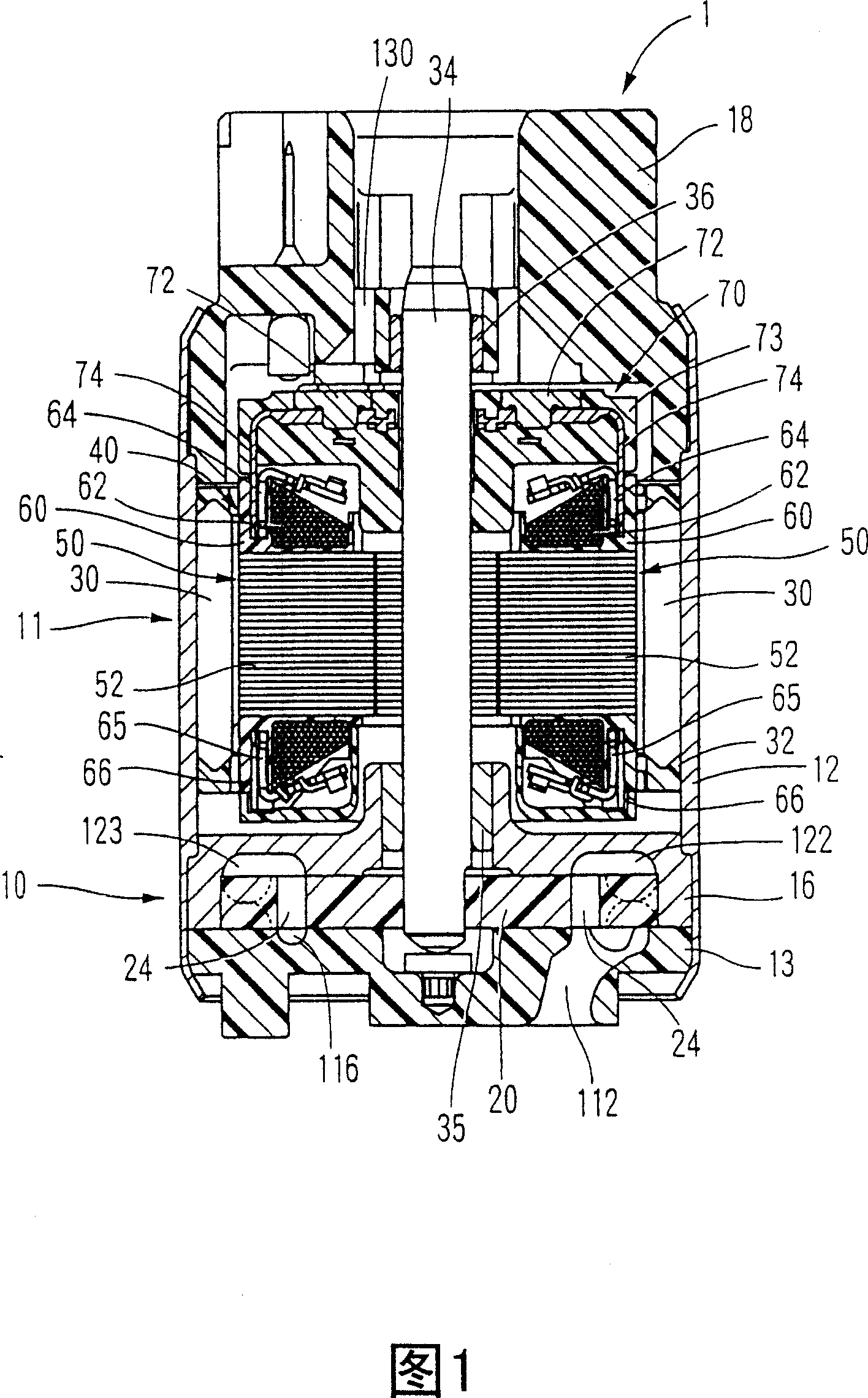
[0033] A fuel pump 1 according to a first embodiment will now be described with reference to FIG. 1 . The fuel pump 1 may be, for example, an in-tank type pump installed inside a fuel tank for a vehicle. The fuel pump 1 has a pump part 10 and a motor part 11 which is an electric motor.

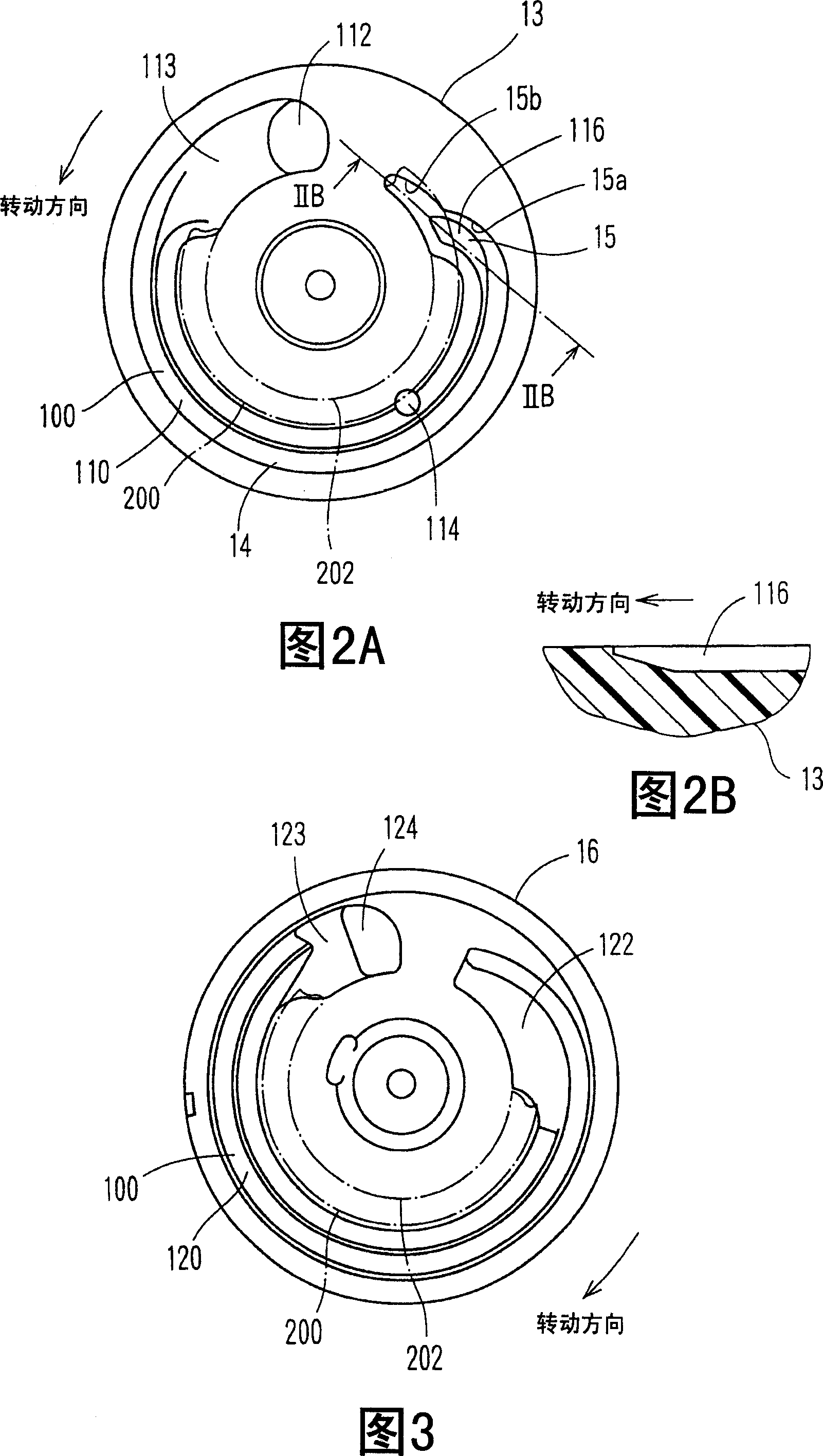
[0034] The pump section 10 includes a suction side cover 13 , a pump casing 16 and an impeller 20 . The pump casing 16 and the suction-side end cover 13 are fixed to the lower end portion of the housing 12 and are in a state that the pump casing 16 enclosing the impeller 20 at its lower inner peripheral portion is accommodated and sandwiched between the suction-side end in the axial direction. Between the cover 13 and the housing 12. The bearing member 35 is held by the upper portion of the inner circumference of the pump housing 16 . The suction side cover 13 and the pump casing 16 constitute a casing member that rotatably accommodates the impeller 20, a rotati...


PUM


Abstract

In a fuel pump, an impeller is rotatably accommodated between a suction side cover and a pump casing. A pump channel of the suction side cover is positioned on an axial side opposite to a fuel discharge port with respect to the impeller. The impeller has blade grooves circumferentially outside and communicating holes circumferentially inside. A wall of a terminal end portion of the pump channel of the suction side cover has a guide portion directing from the blade grooves toward the communicating holes. The terminal end portion is pointed in shape in a rotation direction of the impeller. Fuel pressurized in the pump channel is guided from the blade grooves to the communicating holes at the terminal end portion without steeply reducing flow speed and flows through the communicating holes to the fuel discharge port.

Description

technical field [0001] The present invention relates to a fuel pump in which the pressure of fuel sucked therein is increased by rotating a rotating member having a plurality of vane grooves arranged in a rotating direction thereof. Background technique [0002] Patent documents such as EP-1286041A, JP-A-2001-342983 and JP-A-Hei08-014184 disclose some fuel pumps in which the Increase the pressure of the fuel being sucked in. These conventional fuel pumps have a case member in which a rotary member is rotatably accommodated. The case member has a pump passage extending from the fuel suction port to the fuel discharge port to form grooves along the vane groove so that fuel is sucked from the fuel suction port according to the rotation of the rotating member and pressurized while the fuel passes through the pump passage, and then passed through the fuel pump passage. The pressurized fuel is discharged from the exhaust port. [0003] In a conventional fuel pump, pressurized f...

Claims


Application Information

Patent Timeline
Patent Type & Authority Patents(China)
IPC IPC(8): F04D5/00F02M37/00F02M37/08F02M37/10F04D7/02F04D29/22F04D29/44
CPCF05B2250/503F04D5/007F04D5/002
Inventor 高木雅敏大井清利
Owner DENSO CORP
Learn More