Ophthalmologic apparatus
一种眼睛检测、眼睛的技术,应用在测试眼睛的设备、综合屈光检查仪、医药科学等方向,能够解决眼睛检测长时间化、很难识别、很难被检测者顺利选择视标提示状态等问题
- Summary
- Abstract
- Description
- Claims
- Application Information
AI Technical Summary
Problems solved by technology
Method used
Image
Examples
Embodiment 1
[0035] [the whole frame]
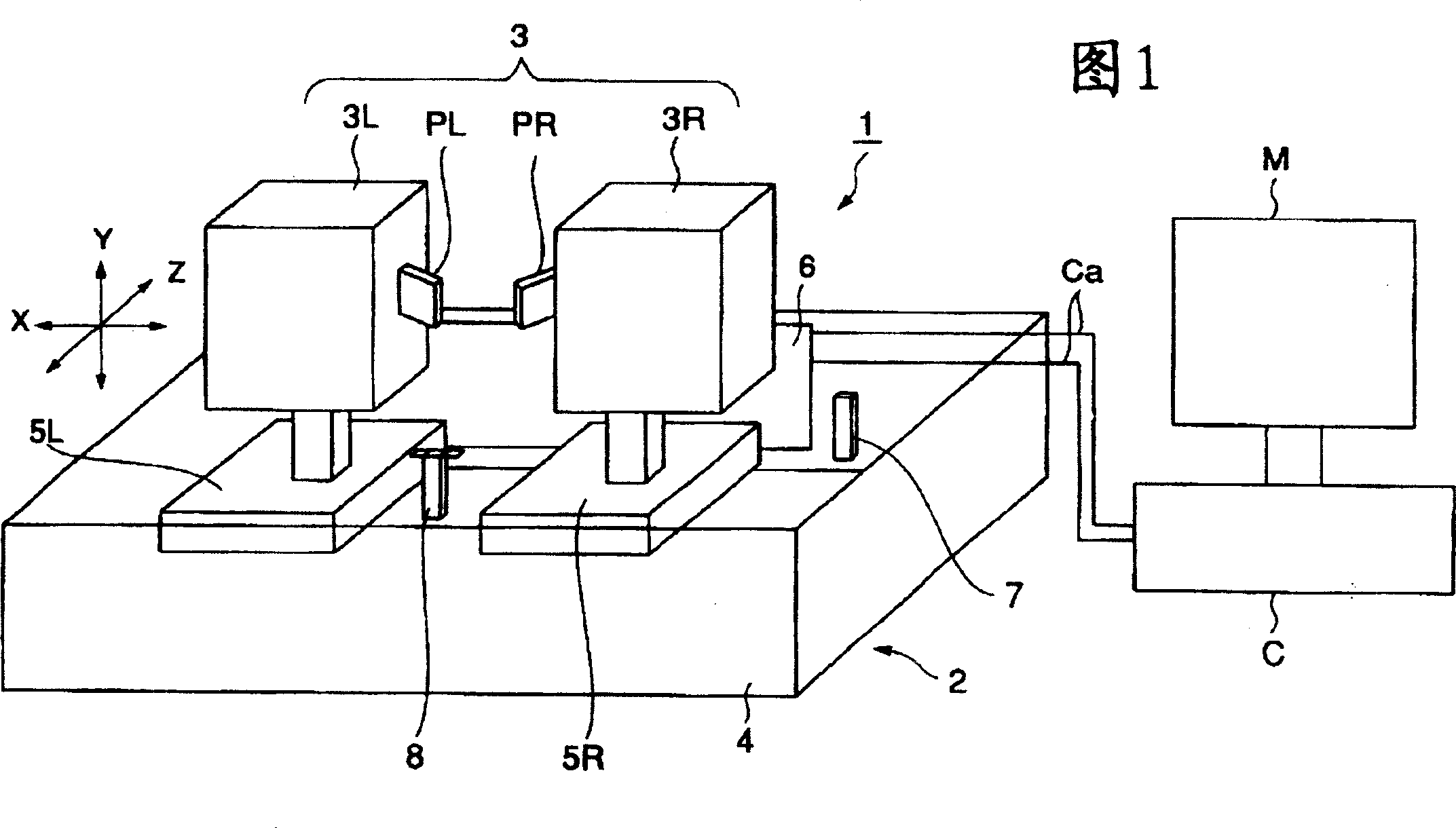
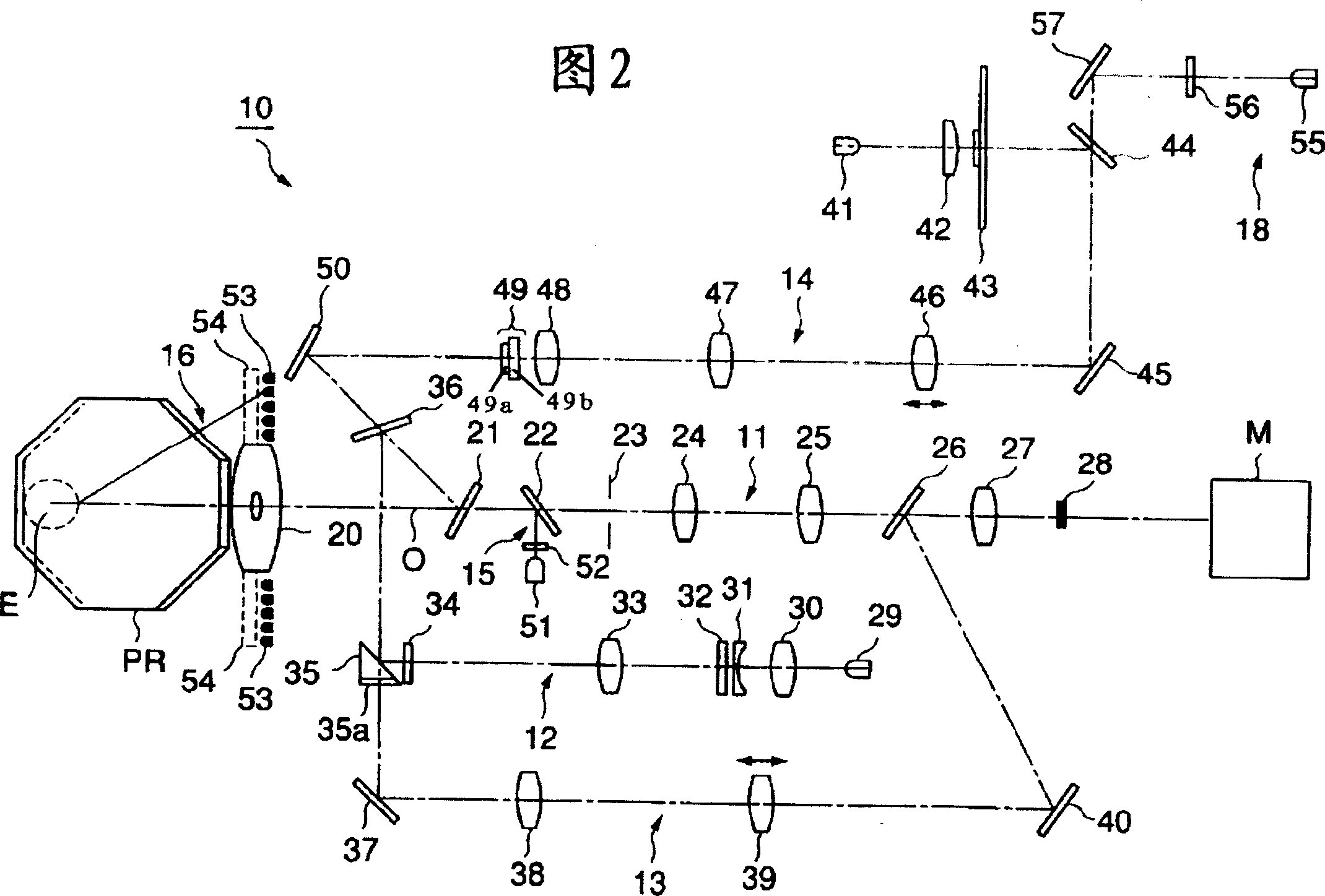
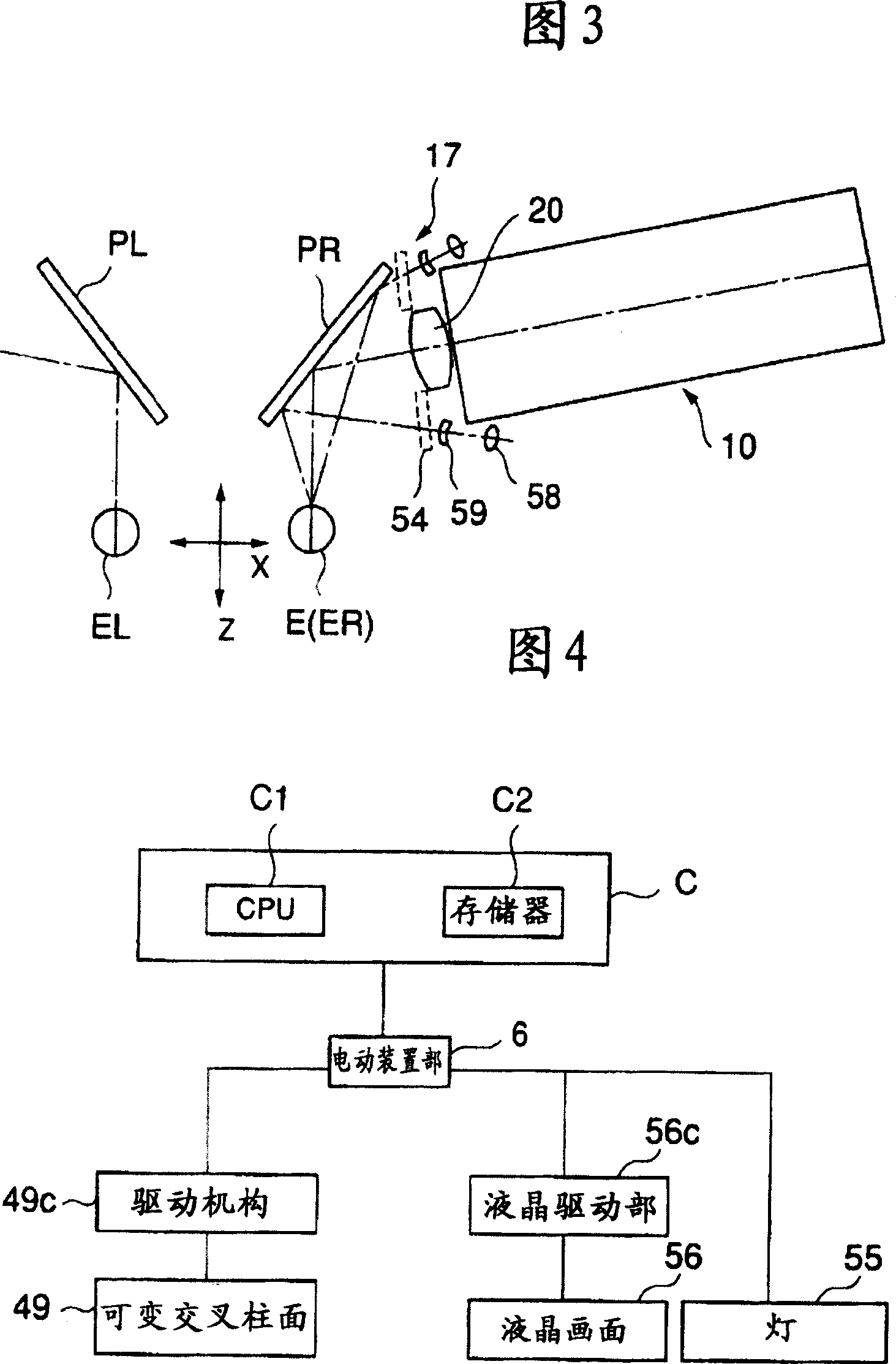
[0036] FIG. 1 is a perspective view showing an outline of the overall configuration of an eye detection device 1 according to Embodiment 1. As shown in FIG. The eye testing device 1 is a device capable of performing astigmatism testing in addition to self-perceived power measurement and other-perceived power measurement alone or in connection with assistants guiding multiple subjects. The eye detection based on the eye detection device 1 is automatically carried out along the given steps. First, the approximate value of the refractive power of the detected eye E is obtained through the measurement of the power of the other person's perception method, and the measurement of the power of the self-perception method is performed based on the approximate value. For measurement, after the astigmatism power is obtained by the astigmatism test, the spherical power is adjusted, and the visual acuity test is performed with the last obtained power. It should b...
Embodiment 2
[0086] Next, Embodiment 2 of the present invention will be described with reference to FIG. 11. FIG. FIG. 11 shows an identifier display member 60 instead of the liquid crystal screen 56 of the eye detection device 1 . 11( a ) is a perspective view showing a schematic structure of the identifier display member 60 viewed from the front, and FIG. 11( b ) is a side view showing a schematic structure of the identifier display member 60 . It should be noted that in FIG. 11( b ), the liquid crystal screen 56 of the eye detection device 1 is replaced with an identifier display member 60 , and the lamp 55 and the identifier display member 60 constitute identification information generating means.
[0087] As shown in the two figures, the identifier display member 60 includes: an identification target plate 61 for displaying an identifier “1” 61a and an identifier “2” 61b; and a shutter 62 for covering a part of the identification target plate 61 . The front end of the rotary shaft 64...
Embodiment 3
[0093] The purpose of Embodiment 3 of the present invention described below is to improve the ability to recognize an optotype by simultaneously projecting a colored fusion frame and an optotype. The fusion frame is an optotype for promoting the fusion of the respectively recognized optotype images from the left eye EL and right eye ER when eye detection is performed by simultaneously projecting optotypes to both eyes of the subject. It should be noted that this embodiment has almost the same structure as the above-mentioned Embodiment 1, so only its characteristic part (identifier generating optical system) will be described.
[0094] As described above, the identifier generating optical system 18 is built in each of the left-eye head 3L and the right-eye head 3R. In this embodiment, as the lamp 55 of the identifier generating optical system 18, for example, a multi-color LED that switches between red light and green light is arranged. The switching operation by this multico...
PUM
 Abstract
Description
Claims
Application Information
 - R&D
- Intellectual Property
- Life Sciences
- Materials
- Tech Scout
- Unparalleled Data Quality
- Higher Quality Content
- 60% Fewer Hallucinations
Browse by: Latest US Patents, China's latest patents, Technical Efficacy Thesaurus, Application Domain, Technology Topic, Popular Technical Reports.
© 2025 PatSnap. All rights reserved.Legal|Privacy policy|Modern Slavery Act Transparency Statement|Sitemap|About US| Contact US: help@patsnap.com


