Rubber track

A technology of rubber crawler and rubber elastic body is applied in the field of rubber crawler, which can solve the problems of inability to adapt to the running speed and the vibration of the operator, and achieve the effects of high strength, improved strength and improved reliability.

Inactive Publication Date: 2008-01-16
BRIDGESTONE CORP
View PDF5 Cites 0 Cited by
  • Summary
  • Abstract
  • Description
  • Claims
  • Application Information

AI Technical Summary

Problems solved by technology

However, when the steel cord is formed into a loop, laps are formed according to the usual method, so this rubber crawler has the disadvantages of vibrating the operator and being unable to adapt to relatively high travel. speed
Even so, in fact such rubber tracks still need to be further improved.

Method used


Image

  • Rubber track
  • Rubber track
  • Rubber track

Examples


Embodiment Construction

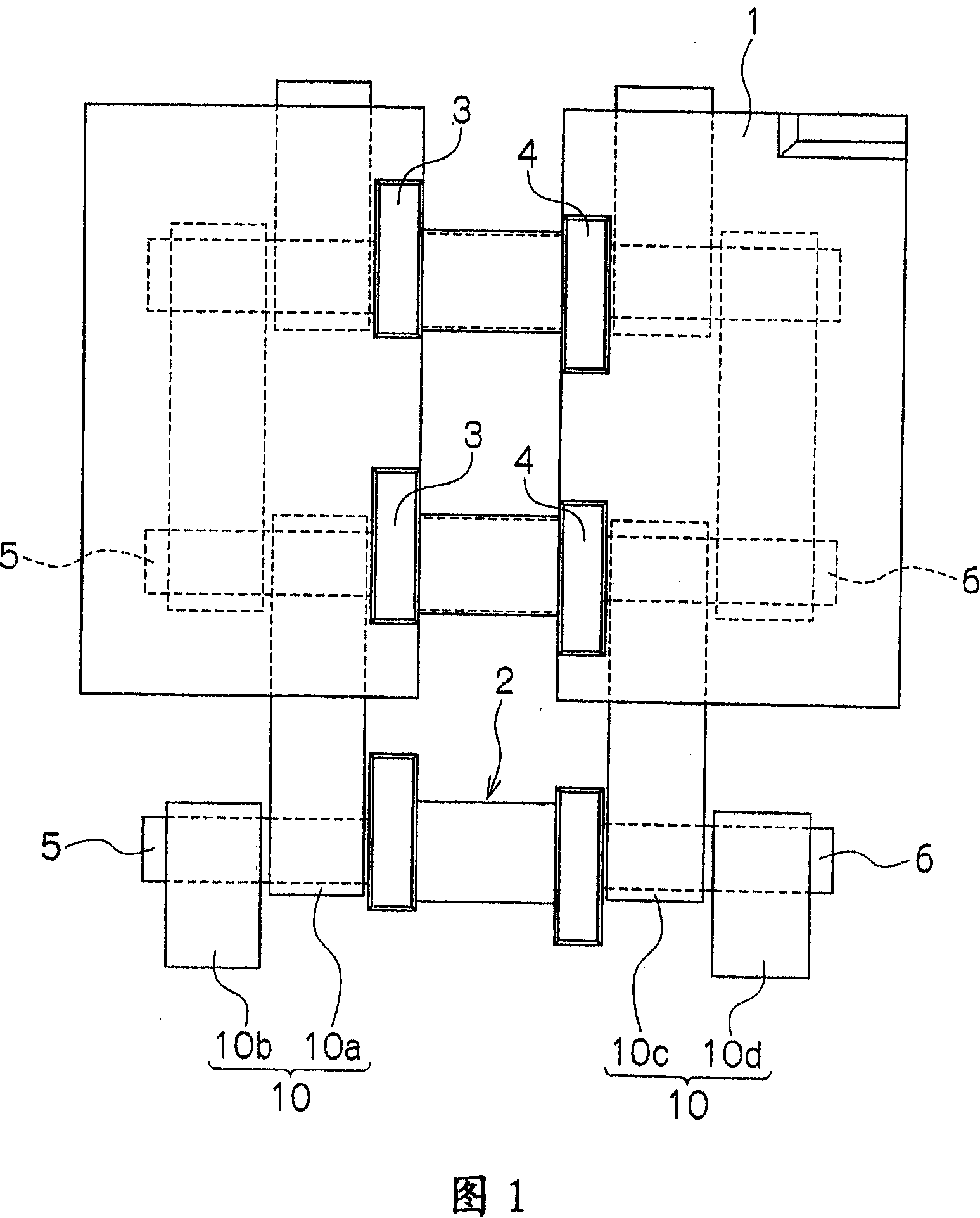
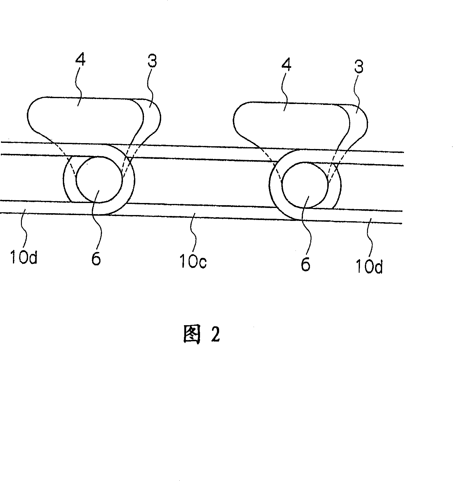
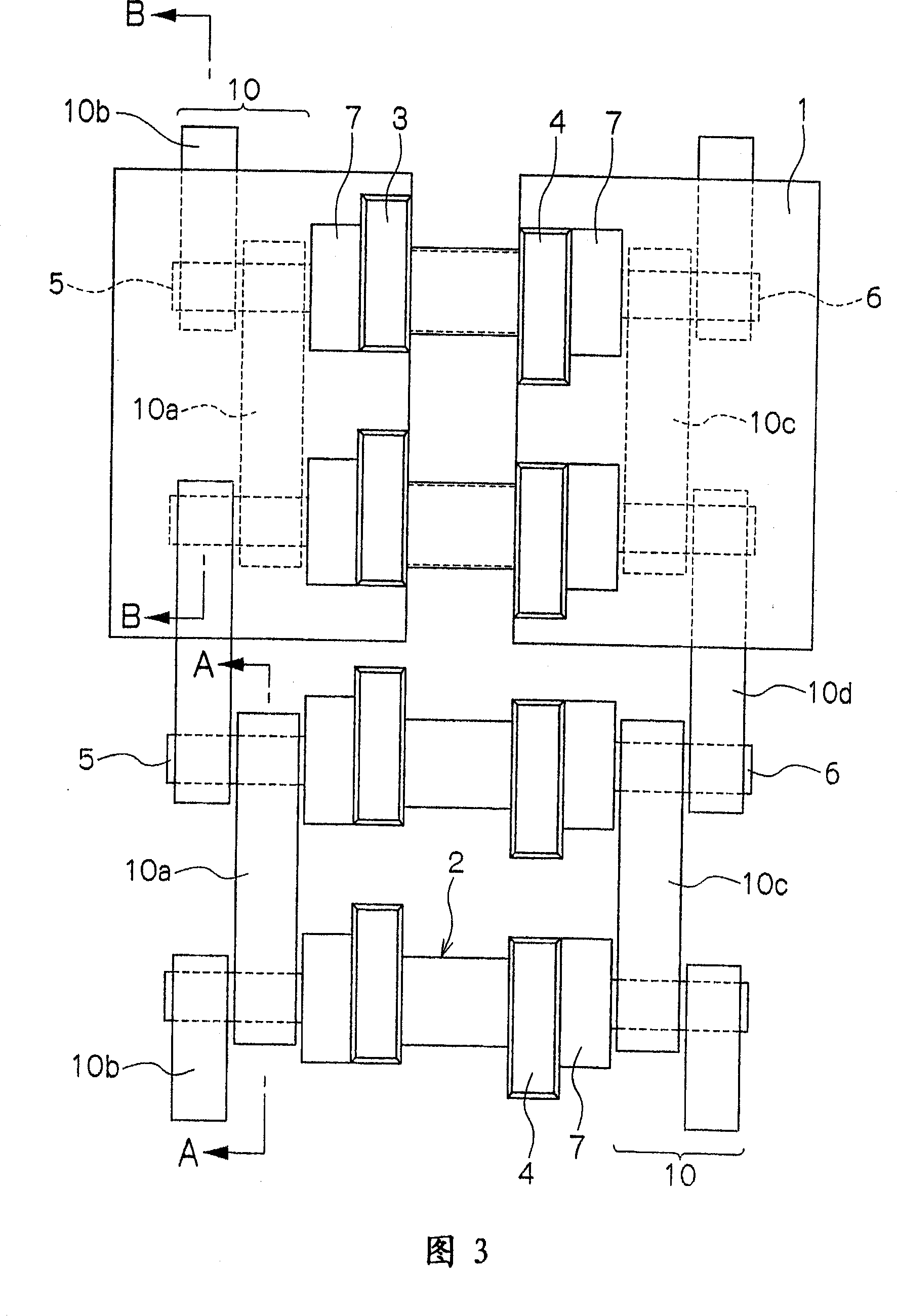
[0052] Embodiments of the present invention will be further described in detail below in conjunction with the accompanying drawings. Fig. 1 is a plan view of the inner peripheral surface side of a rubber crawler according to a first example of the present invention. FIG. 2 is a side view of FIG. 1 . Fig. 3 is a plan view of the inner peripheral surface side of a rubber crawler according to a second example of the present invention. FIG. 4 is a side view of FIG. 3 . Fig. 5 is a sectional view at line A-A. Fig. 6 is a sectional view at line B-B. Fig. 7 is a sectional view at line C-C.

[0053] Among the figure, 1 is rubber elastic body, and it is the substrate of rubber track. In FIGS. 1 and 3 , the rubber elastic body 1 is continuously formed in an annular shape in the vertical direction on the paper surface. 2 is a metal core, on which a pair of protrusions 3, 4 protruding from the inner peripheral surface of the rubber elastic body 1 are formed, and wing portions 5, 6 a...


PUM


Abstract

A rubber crawler has a structure in which connecting members are sequentially fitted onto wing portions adjacent to each other without using steel cords for resisting tensile force applied to the rubber crawler. Accordingly, the rubber crawler of the present invention has excellent characteristics in that breakage of steel cords due to the tensile force can be prevented, and torsion of the rubber crawler can be reduced.

Description

technical field [0001] The present invention relates to a rubber crawler mainly used in construction machinery and civil engineering machinery, and more particularly, to a rubber crawler adopting a completely new construction of a tensile member. Background technique [0002] Conventionally, in order for the rubber crawler to withstand the tension applied thereto, steel cords were buried longitudinally therein as tensile members. However, when the steel cord is formed into a loop, laps are formed according to the usual method, so this rubber crawler has the disadvantages of vibrating the operator and not being suitable for relatively high travel. speed. Since the tensile member is formed of steel cords, there is obviously also the problem that it breaks when subjected to high tension. [0003] On the other hand, Japanese Patent Application Laid-Open No. 20000-313371 discloses a rubber track that does not employ a steel cord structure. However, in the rubber track describe...

Claims


Application Information

Patent Timeline
IPC IPC(8): B62D55/253
Inventor 鹤荣次内田伸二
Owner BRIDGESTONE CORP
Why Eureka
Try Eureka