
Fluid bearing device and disc-rotation device using same

A fluid bearing, bearing hole technology, applied in bearings, electromechanical devices, bearing components, etc., can solve problems such as friction

Active Publication Date: 2008-01-02
PANASONIC CORP
View PDF8 Cites 0 Cited by
  • Summary
  • Abstract
  • Description
  • Claims
  • Application Information

AI Technical Summary

Problems solved by technology

Therefore, air bubbles gather in this region 43A, and there is a risk of friction between the shaft 31 and the bushing 32 due to oil film breakage at this region 43A.

Method used


Image

  • Fluid bearing device and disc-rotation device using same
  • Fluid bearing device and disc-rotation device using same
  • Fluid bearing device and disc-rotation device using same

Examples


Embodiment Construction

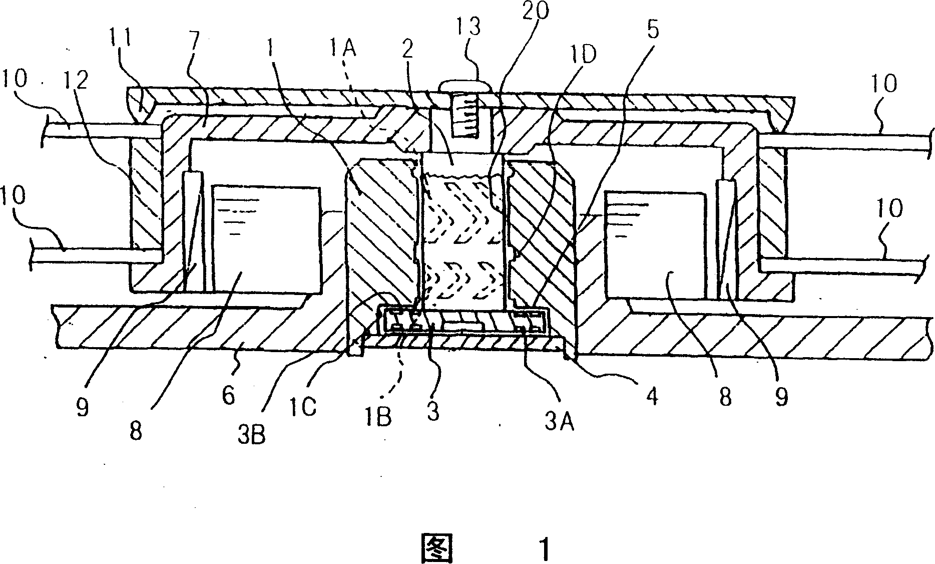
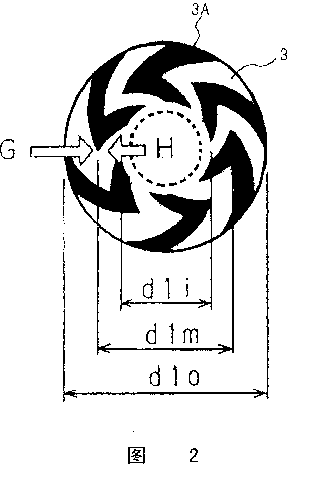
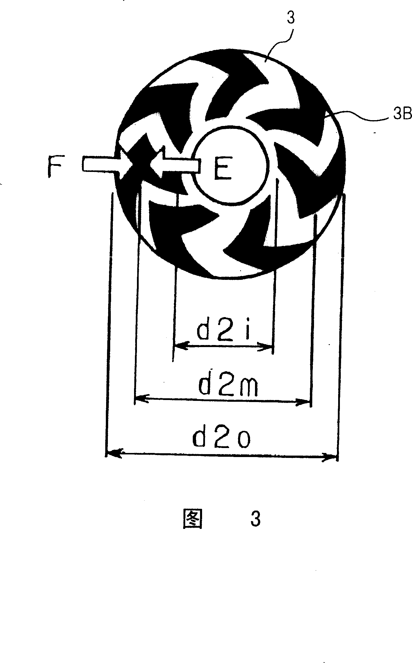
[0035] DETAILED DESCRIPTION OF THE PREFERRED EMBODIMENTS A preferred embodiment of the fluid bearing device of the present invention will be described below with reference to FIGS. 1 to 10. FIG. FIG. 1 is a cross-sectional view showing a fluid bearing device according to an embodiment of the present invention. In FIG. 1 , a bushing 1 has a bearing hole 20 approximately at the center, and herringbone-shaped dynamic pressure generating grooves 1A, 1B are formed on the inner peripheral surface of the bearing hole 20 . A recessed portion 1C is formed at the lower end portion of the boss 1 . The shaft 2 is rotatably inserted into the bearing hole 20 . The flange 3 is fixed to the lower end portion of the shaft 2 so as to fit into the recess 1C of the lower portion of the sleeve 1 . The thrust plate 4 is fixed in the recess 1C of the bushing 1 by laser welding, precision riveting, bonding and other fixing methods, so that the recess 1C including the flange 3 is sealed. The shaft ...


PUM


Abstract

A high-accuracy, long-life hydrodynamic bearing that does not cause oil film breakage in bearing clearances and a disc rotation apparatus using the bearing is disclosed. Oil film breakage is avoided as negative pressure is prevented from generating between the shaft and sleeve of the hydrodynamic bearing. Herringbone shaped dynamic pressure generating grooves, located on the thrust bearing section and the radial bearing section of the hydrodynamic bearing, are oil filled and have optimum shapes. The optimum shapes prevent the generation negative pressure and thus prevents the coagulation of air bubbles that can cause oil film breakage. The disc rotation apparatus, that holds a reproduction / recording disc, is concentrically secured to the hydrodynamic bearing and rotated. The disc is put into contact with magnetic or optical heads while rotating in the disc rotation apparatus. Both the hydrodynamic bearing and the disc rotation apparatus experience high reliability.

Description

technical field [0001] The present invention relates to a fluid bearing device having a fluid in a rotating part, and a disc rotating device using the fluid bearing device. Background technique [0002] In recent years, the storage capacity of recording devices such as optical discs has been increasing, and at the same time, the data transmission speed has been further increased. Therefore, a disc rotation device used in such a recording device requires high-speed and high-precision rotation, and a fluid bearing device is used for the rotation main shaft portion. [0003] Hereinafter, an example of a conventional fluid bearing device and a disk rotating device using the same will be described with reference to FIG. 12 . FIG. 12 is a cross-sectional view showing a right side portion of a center line C which is the center of a rotating shaft of a conventional fluid bearing device. In FIG. 12, a shaft 31 is rotatably inserted into a sleeve 32 having a bearing hole 32A. An in...

Claims


Application Information

Patent Timeline
IPC IPC(8): F16C32/06G11B7/135F16C17/10F16C17/04F16C33/10G11B19/20H02K5/16H02K7/08
CPCF16C33/107G11B19/2018F16C17/107F16C2370/12F16C17/04F16C17/045F16C33/106
Inventor 浅田隆文斋藤浩昭日下圭吾伊藤大辅
Owner PANASONIC CORP
Learn More