Dust separator of vacuum cleaner

A dust separation and vacuum cleaner technology, applied in suction filters and other directions, can solve the problems of heavy separation burden of downstream separators, poor cyclone separation effect, and large airflow flow, so as to improve the cyclone separation effect, enhance the dust collection ability, and reduce the airflow. The effect of traffic

Inactive Publication Date: 2007-12-26
卞庄
View PDF6 Cites 0 Cited by
  • Summary
  • Abstract
  • Description
  • Claims
  • Application Information

AI Technical Summary

Problems solved by technology

[0002] The dust separation device on the existing vacuum cleaner usually includes a first separator and a downstream separator, wherein the downstream separator is a cyclone separator, and the dusty airflow is roughly separated in the first separator, so that the large ash is separated, The airflow entering the downstream separator is separated with high efficiency, so that the fine dust is separated. Since the separation efficiency of the first separator is low, the separation burden of the downstream separator is heavy, and because the separation in the first separator All the airflow after the large ash enters the downstream separator, so the flow rate of the airflow entering the downstream separator is relatively large, which makes the effect of cyclone separation in the downstream separator poor, resulting in low dust filtration efficiency of the entire dust separation device

Method used


Image

  • Dust separator of vacuum cleaner
  • Dust separator of vacuum cleaner
  • Dust separator of vacuum cleaner

Examples


Embodiment Construction

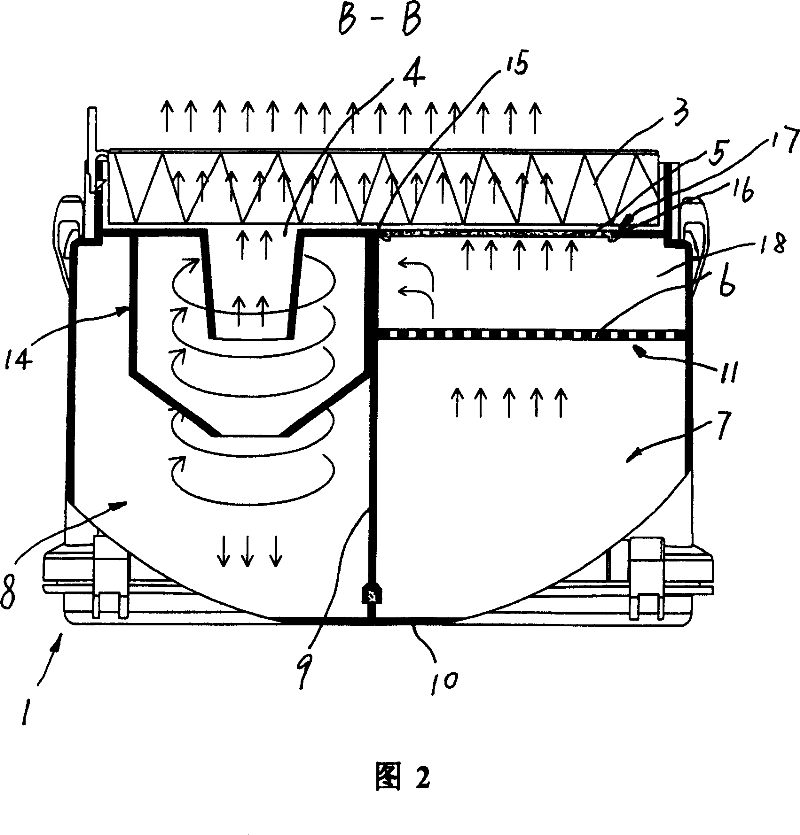
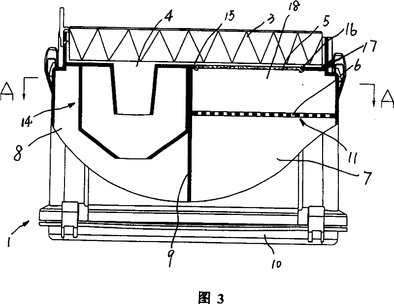
[0014] Referring to accompanying drawing 1-accompanying drawing 5, a kind of dust separating device on the vacuum cleaner, it comprises first separator 17, the cyclone separator 14 that is positioned at the side of described first separator 17, described first separator 17 includes an upstream dust chamber 7 and an airflow distribution chamber 18, the upstream dust chamber 7 and the airflow distribution chamber 18 are separated by a mesh plate 11 with a plurality of mesh holes 6, and the upstream dust chamber 7 has Dust air inlet 2, the air distribution chamber 18 has a first air outlet 13 and a second air outlet 16, the second air outlet 16 is provided with a first filter 5, and the cyclone separator 14 It has a cyclone inlet 12 and a cyclone outlet 4 , the first air outlet 13 communicates with the cyclone inlet 12 , and the second air outlet 16 and the cyclone outlet 4 directly lead to the air outlet channel 15 .

[0015] The second filter 3 is arranged on the air outlet cha...


PUM


Abstract

The dust separator of vacuum cleaner includes the first separator, and one cyclonic separator. The first separator includes one upstream dust chamber with dusty wind inlet and one airflow distributing chamber with the first airflow outlet, the second airflow outlet and the first filter in the second airflow outlet. The cyclonic separator has one cyclone inlet communicated with the first airflow outlet and one cyclone outlet. Partial airflow after separating large grain dust in the first separator flows out directly from the second airflow outlet, and this reduces the quality of airflow entering the cyclonic separator, raises the cyclonic separating effect and increases the airflow quality of the whole separator.

Description

technical field [0001] The invention relates to a dust separating device on a vacuum cleaner. Background technique [0002] The dust separation device on the existing vacuum cleaner usually includes a first separator and a downstream separator, wherein the downstream separator is a cyclone separator, and the dusty airflow is roughly separated in the first separator, so that the large ash is separated, The airflow entering the downstream separator is separated with high efficiency, so that the fine dust is separated. Since the separation efficiency of the first separator is low, the separation burden of the downstream separator is heavy, and because the separation in the first separator All the airflow after the large ash enters the downstream separator, so the flow rate of the airflow entering the downstream separator is relatively large, which makes the effect of cyclone separation in the downstream separator poor, resulting in low dust filtration ef...

Claims


Application Information

Patent Timeline
Patent Type & Authority Patents(China)
IPC IPC(8): A47L9/16
Inventor 卞庄
Owner 卞庄
Why Eureka
Try Eureka