Safety valve for timer

A safety valve and timer technology, applied in the field of safety valves, can solve problems such as the deterioration of the sealing characteristics of the safety valve, and achieve the effect of good sealing characteristics

Inactive Publication Date: 2007-12-05
メコエスアーグレンヒェン
View PDF5 Cites 0 Cited by
  • Summary
  • Abstract
  • Description
  • Claims
  • Application Information

AI Technical Summary

Problems solved by technology

[0008] If the cap is not screwed down before diving operations, small amounts of water and dirt particles can get inside the timer and deteriorate the sealing properties of the safety valve

Method used


Image

  • Safety valve for timer
  • Safety valve for timer

Examples


Embodiment Construction

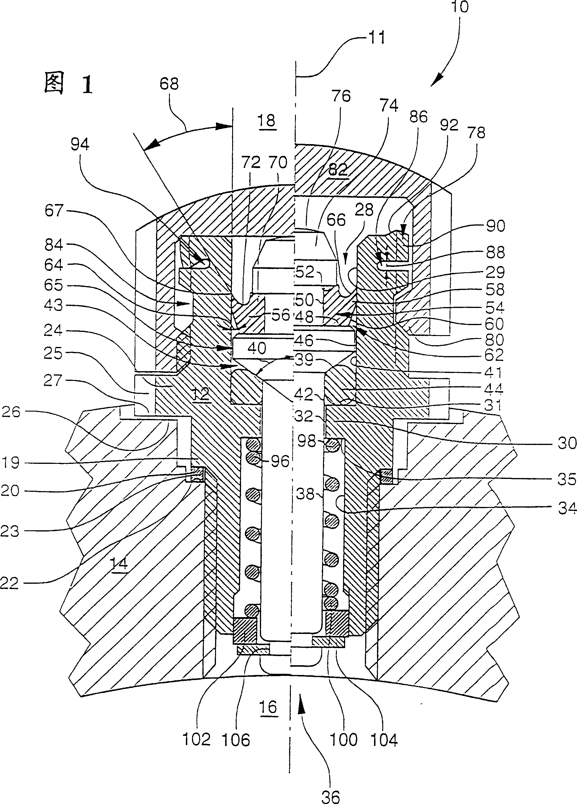
[0043] Figure 1 shows one embodiment of the safety valve of the present invention. The safety valve 10 is substantially rotationally symmetric with respect to the axis 11 and comprises a continuous hollow sleeve 12 screwed onto the only partially shown central part 14 or the exterior of the timepiece. An interior space 16 located below the figure is formed in the timepiece, which space is airtightly separated from the environment 18 located above the figure.

[0044] The outer side of the sleeve 12 includes a shoulder 19 with a bearing surface 20 which is annular relative to the axis and faces the housing 14 . A metal sealing ring 23 is arranged between this bearing surface and the corresponding annular bearing surface 22 of the housing 14 , the sealing ring 23 in this position isolating the space 16 from the environment 18 .

[0045] In order to screw the sleeve 12 , or rather the safety valve 10 , into the central part using, for example, a fitting key, the sleeve 12 includ...


PUM


Abstract

A safety valve with an element rigid with the housing and with an operable element which is movable with respect to this. Between these two elements there is arranged a lip seal with an elastic lip, which bears on the element rigid with the housing and delimits the timepiece inner space from the surroundings. By way of the fact that the lip is led in the direction of the surroundings conically onto the element rigid with the housing and lies on this element with pretensioning, on the one hand with an inner space excess pressure it may release itself from the element rigid with the housing for the purpose of pressure compensation between the inner space and the surroundings and on the other hand with a surrounding excess pressure it is more strongly pressed on the element rigid with the housing for the purpose of sealing the inner space with respect to the surroundings.

Description

[0001] In this application, the filing date of June 10, 1998 is the divisional application of the application number 98109811.8. technical field [0002] The present invention relates to a safety valve such as for a timepiece. Background technique [0003] From CH682199 a timer is known which is equipped with a safety valve to prevent an overpressure above the ambient pressure from being generated in the timer under certain conditions. [0004] Overvoltages develop within the timer for the following reasons: [0005] If the internal pressure of the timer initially corresponds to the external pressure, and then from this state it is subjected to higher ambient pressure, some substance will diffuse through the seal and into the interior of the timer, causing the Pressure increases, or pressure regulation occurs. If the timer is subsequently subjected to a relatively low ambient pressure for a relatively short period of time, an overpressure in the timer relative to the envir...

Claims


Application Information

Patent Timeline
IPC IPC(8): F16K17/04G04B37/10
CPCG04B37/103
Inventor H·李奔
Owner メコエスアーグレンヒェン
Why Eureka
Try Eureka