
Multifreedom stereo vision device having laser

A technology of stereo vision and degree of freedom, applied in the direction of manufacturing tools, manipulators, etc., can solve problems such as difficulty in accurate positioning, feature mismatch, and blurred target features, and achieve the effect of simple structure and easy operation

Inactive Publication Date: 2007-12-05
朱兴龙 +2
View PDF7 Cites 0 Cited by
  • Summary
  • Abstract
  • Description
  • Claims
  • Application Information

AI Technical Summary

Problems solved by technology

However, it is very difficult to perform feature extraction and accurate positioning using existing methods. This is due to the complexity of the actual image surface and the influence of noise. When performing image matching, the target features will appear blurred, and it is very easy It causes the phenomenon of feature mismatch, and this phenomenon has not been solved well, which makes the feature-based matching method have limitations in practical applications.

Method used


Image

  • Multifreedom stereo vision device having laser
  • Multifreedom stereo vision device having laser
  • Multifreedom stereo vision device having laser

Examples


Embodiment Construction

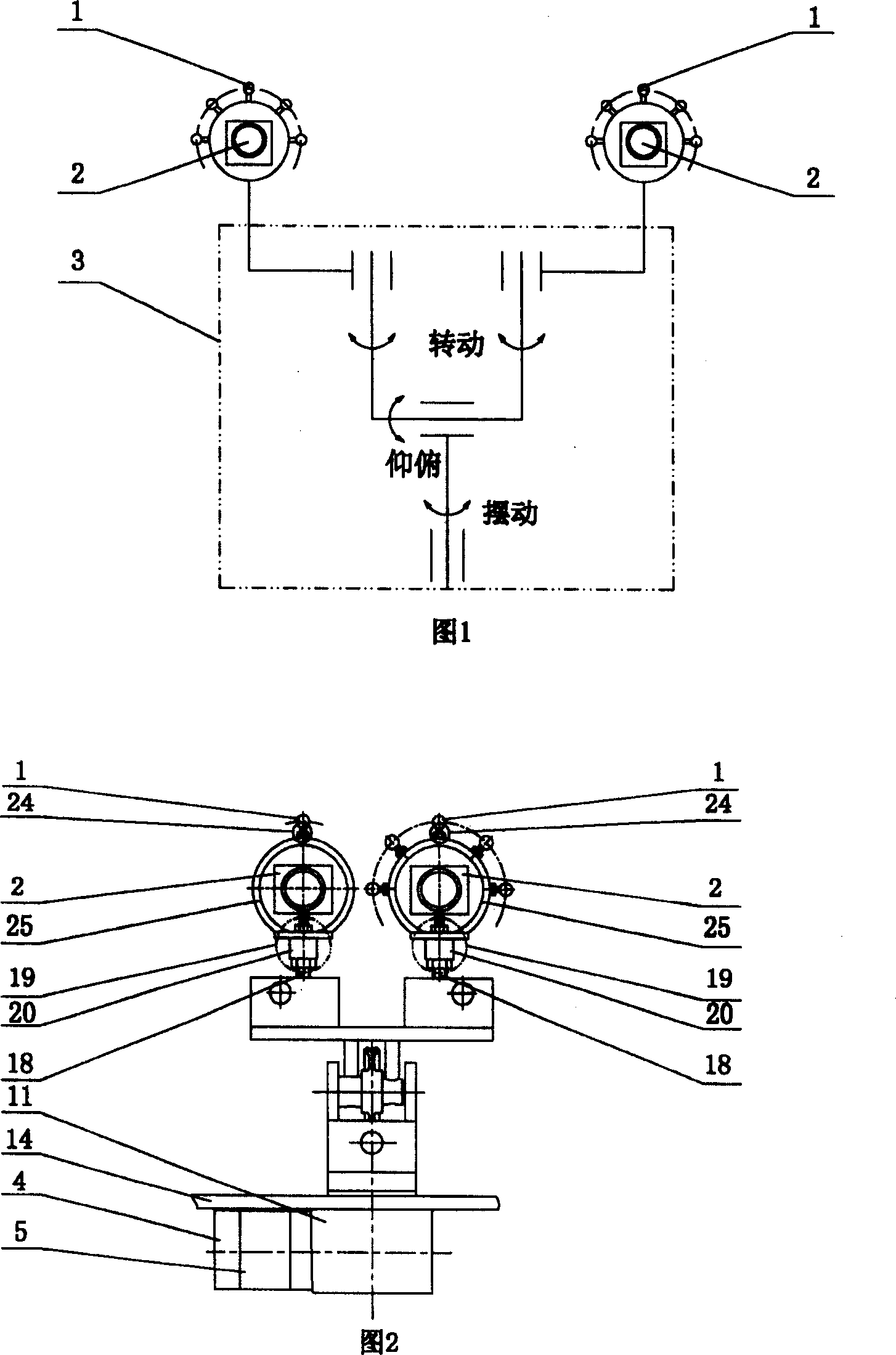
[0016] Shown in Figure 1 is the camera 2, there are two, also known as binocular, and there are multiple lasers 1, the laser 1 is a small laser; the camera 2 and the laser 1 are installed on the four-degree-of-freedom mechanical body 3, forming a plurality of lasers 1 The multi-degree-of-freedom stereo vision device can make the camera 2 and the laser 1 move in four degrees of freedom; the point line of the laser 1 is parallel to the optical axis of the camera 2 .

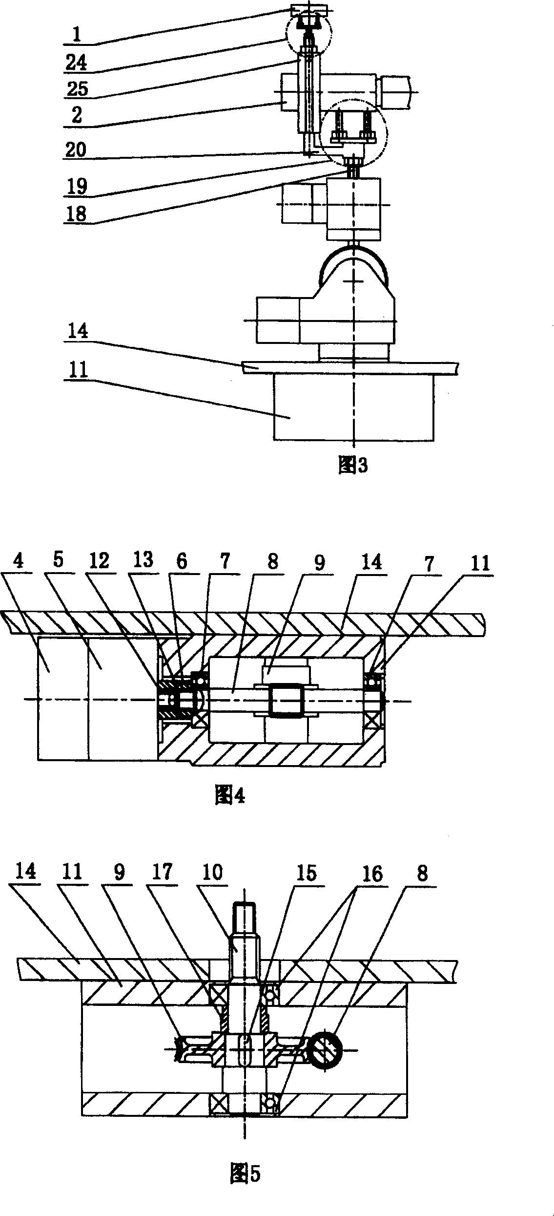
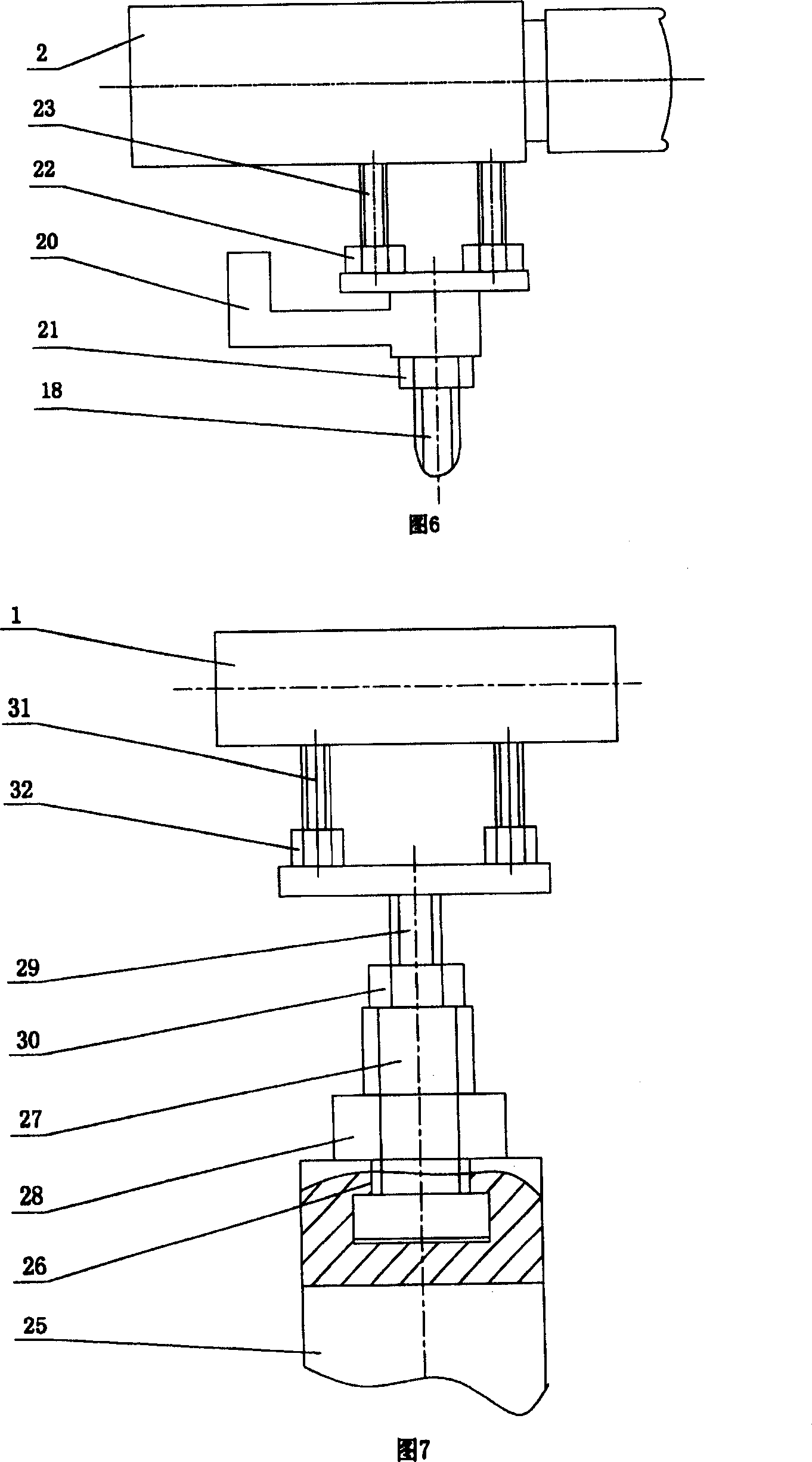
[0017] Since the four-degree-of-freedom motion realization structure of the multi-laser multi-degree-of-freedom stereoscopic vision device is the same, the specific implementation process of the multi-laser multi-degree-of-freedom stereoscopic vision device is described here by realizing the swinging freedom motion structure.

[0018] As shown in Figures 1, 2, 3, 4, 5, 6, and 7, one end of the motor 5 is connected to the encoder 4, and the motor 5 is connected through the spline wheel 12, the spline sleeve 6, and th...


PUM


Abstract

A multi-freedom stereo visual device with laser for robot is composed of output axle, camera connected to said output axle, free movnig unit, motor, the drive axles and casing for swinging freedom, elevation freedom and rotation freedom, laser device, and the regulators for camera and laser devices.

Description

technical field [0001] The invention relates to a detection device, in particular to a robot stereo vision detection device for determining the position and posture of a space target object. Background technique [0002] At present, with the development of computer technology, robot stereo vision devices, especially binocular stereo vision devices, have been developed in various forms and have been widely used. [0003] These vision devices usually include cameras and sensors, and image processing includes image preprocessing and feature extraction, feature matching, three-dimensional size calculation, and depth information interpolation. Among them, feature matching is the most complex link in the vision algorithm. [0004] Before the realization of the present invention, feature matching mainly adopts image matching, that is, according to a known image pattern (real-time image), and then searches for a corresponding or similar pattern in another image (reference image). ...

Claims


Application Information

Patent Timeline
Patent Type & Authority Patents(China)
IPC IPC(8): B25J19/04
Inventor 朱兴龙周骥平孔繁群
Owner 朱兴龙
Learn More