Attractor

An attractor and shell technology, which is applied to fishing accessories, fishing, manipulators, etc., can solve the problems of increased cost, reduced manufacturing efficiency of the attractor, and difficulty in miniaturizing the attractor, and achieves a simple structure, improved thermal efficiency, etc. The effect of resistance

Active Publication Date: 2007-10-24
株式会社日本碧士克
View PDF4 Cites 4 Cited by
  • Summary
  • Abstract
  • Description
  • Claims
  • Application Information

AI Technical Summary

Problems solved by technology

Therefore it is difficult to miniaturize the attractor in said direction
In addition, the bellows is formed by cutt

Method used


Image

  • Attractor
  • Attractor

Examples


Embodiment Construction

[0025] Embodiments of the present invention will now be described in detail with reference to the accompanying drawings.

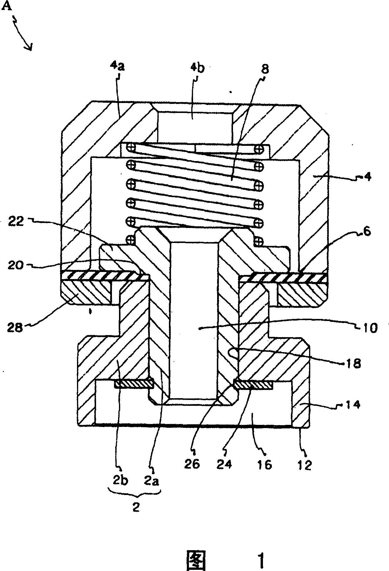
[0026] Fig. 1 is a side sectional view of an embodiment of an aspirator A of the present invention.

[0027] The suction device A includes a suction portion 2, a housing 4, a thin-plate-shaped rubber member 6 made of synthetic rubber as a thin-plate-shaped elastic member, and a spring 8 as a biasing member.

[0028] The suction portion 2 includes a cylindrical member 2a having a through hole 10, and a skirt member 2b in which a contact portion 12 is formed at one end. The contact portion 12 contacts the workpiece when the attraction portion 2 attracts and holds the workpiece.

[0029] A circular protrusion 14 is formed at one end of the skirt member 2b. The through hole 18 communicates with the concave portion 16 surrounded by the circular protrusion 14 and the other end 20 of the skirt 2b.

[0030] The outer diameter of the cylindrical part 2a is almos...


PUM


Abstract

The small and simple sucking unit has a contact part made of a hard material, and the unit is capable of sufficiently sucking and holding a work piece without damaging the work piece. The sucking unit comprises: a sucking section including a through-hole and the contact part, which contacts and holds the work piece when air is sucked via the through-hole; a casing having an air-outlet, from which air sucked through the through-hole is introduced outside, and allowing the sucking section to retract therein and extend therefrom; and a sheet-shaped elastic member connected to the casing and the sucking section so that the sucking section is integrated with the casing.

Description

technical field [0001] The invention relates to a suction device in a suction device, which is able to attract and grip workpieces for eg transport. Background technique [0002] Traditionally, workpieces such as product parts in factories are transported with suction equipment including suction [0003] A conventional sucker includes a through hole through which air is sucked from one end thereof, and a contact portion provided at the other end of the through hole and contacts and holds a workpiece when the air is sucked; Air suction unit. [0004] Generally, the contact portion is made of an elastic material (see the section of Japanese Patent Publication No. 2002-144269 [Conventional Process] and FIGS. 12 and 13). For example, nitrobutadiene rubber (NBR) is used as the contact portion material. [0005] As described in Japanese Patent Publication No. 2002-144269, the contact portion made of such a material has low thermal resistance, and the material of the contact par...

Claims


Application Information

Patent Timeline
IPC IPC(8): B25J15/06
CPCA01D1/04A01D1/14A01K97/00
Inventor 山崎清康北原敏正增沢澄成
Owner 株式会社日本碧士克
Why Eureka
Try Eureka