
Modularized ultrasonic clutch and brake apparatus

A clutch device, ultrasonic technology, applied in the direction of clutch, brake actuator, brake type, etc., can solve the problem that the clutch device has not been engaged or disengaged, and achieve the effect of easy installation

Inactive Publication Date: 2007-10-17
张国财
View PDF9 Cites 33 Cited by
  • Summary
  • Abstract
  • Description
  • Claims
  • Application Information

AI Technical Summary

Problems solved by technology

[0007] Looking at the known clutch devices, there is no clutch device that uses electrical means to control the engagement or disengagement state of the clutch device, or even fine-tunes the torque transmitted through the load shaft.

Method used


Image

  • Modularized ultrasonic clutch and brake apparatus
  • Modularized ultrasonic clutch and brake apparatus
  • Modularized ultrasonic clutch and brake apparatus

Examples


Embodiment Construction

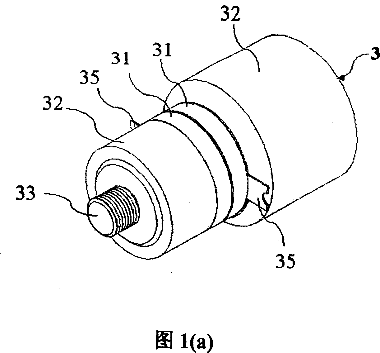
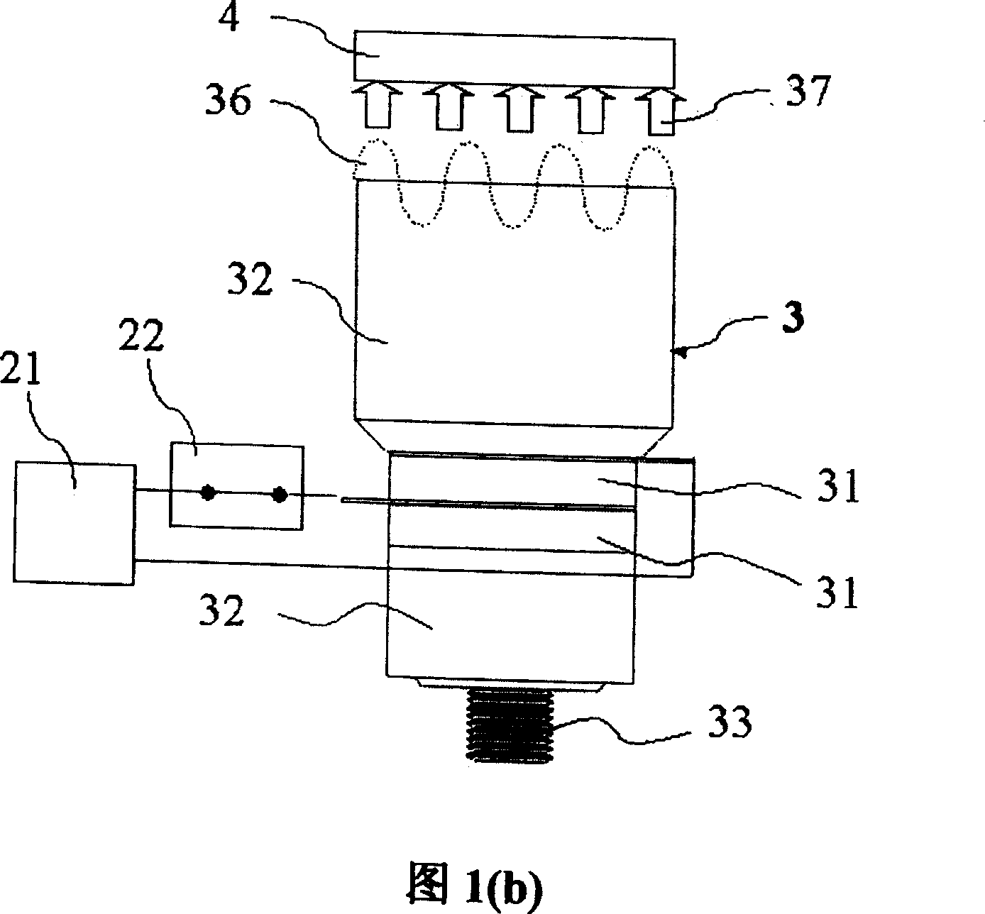
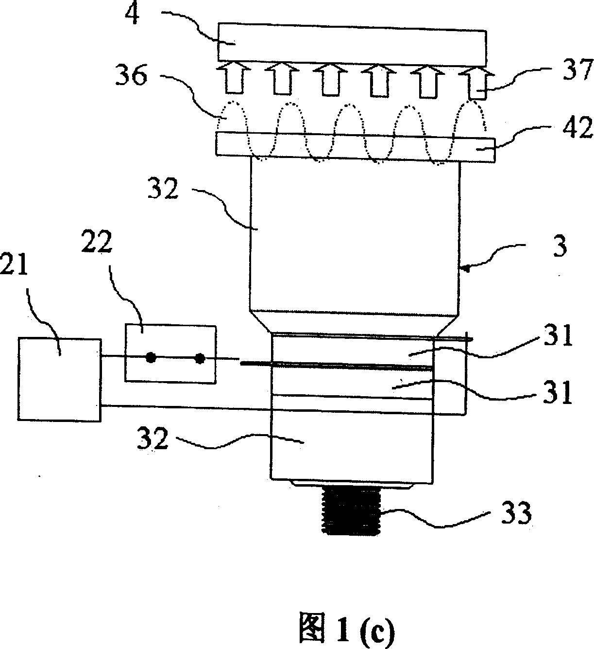
[0050] Please refer to Fig. 3 (a) ~ (c), which is a preferred embodiment of the modular ultrasonic clutch device provided by the present invention. The present invention adopts a symmetrical structural design, mainly including a control power supply group, a drive Component 3 , a driven component 4 , two support frames 51 a , 51 b , a preload adjusting device 6 , two fixing seats 11 a , 11 b and a base 12 .

[0051] Please refer to Fig. 2(a)-(d) and Fig. 3(a)-(c), the modular ultrasonic clutch device uses screws to fix the two supporting frames 51a, 51b on the base 12; secondly, A driving element 3 will be inserted into the inner hole of the bearing on the left side support frame 51a, and a driven element 4 will be inserted into the inner hole of the bearing fixed on the right side of the base 12 support frame 51b; then, drive The end points of the threaded brackets of the element 3 and the driven element 4 can be placed into the fixing seats 11a, 11b, wherein the fixing seats...


PUM


Abstract

The modular ultrasonic clutch and brake mechanism consists of control and power source module, driving element, driven element, support assembly, pre-stress regulator, fixing seat and pedestal. Both the driving element and the driven element have piezoelectric component and contact tightly, so that the load end will rotate synchronously with the motor shaft in use as clutch and will produce braking effect in use as brake. When alternate power source is applied onto the piezoelectric components, the counter-piezoelectric effect of the piezoelectric components will make the combining surface of the mechanism produce mechanism vibration and separation, and this makes the load end stop rotating in use as clutch and the load end produce no braking effect in use as brake.

Description

technical field [0001] The invention relates to a modularized ultrasonic clutch and brake device, which utilizes a piezoelectric element to generate an inverse piezoelectric effect, thereby combining or separating a driving element and a driven element, so as to achieve the functions of a clutch device such as start, stop, and speed change. . Background technique [0002] Known clutch device is of a great variety at present, can be divided into manipulation type and automatic type by its control mode. The functions of the clutch device include starting, stopping, reversing, speed change, or for occasions such as shaft-to-shaft engagement or separation. The types and disadvantages of the clutch device are as follows: [0003] 1. Embedded clutch device: It uses teeth, teeth or keys to transmit torque. There are protruding teeth or teeth on the end faces of its two engaging parts. If the teeth or teeth on the driving element and the driven element are engaged or disengaged f...

Claims


Application Information

Patent Timeline
Patent Type & Authority Patents(China)
IPC IPC(8): F16D48/06F16D65/34F16D65/28
Inventor 张国财
Owner 张国财
Learn More