
Device for advancing drillings in the ground

A technology of land and sealing devices, which is applied to the driving device for drilling in boreholes, earthwork drilling and mining equipment, etc. It can solve the problem of pipeline blockage, unreliable discharge of drill cuttings, and unoptimized drilling head speed, etc. problems and achieve high operational reliability

Inactive Publication Date: 2007-10-17
AKER WIRTH
View PDF9 Cites 0 Cited by
  • Summary
  • Abstract
  • Description
  • Claims
  • Application Information

AI Technical Summary

Problems solved by technology

[0008] Although it has actually been shown that the device known from DE 4332113 A1 is suitable for excavating very different soils, it has the disadvantage that the rotational speed of the drilling head is not optimal for many soil conditions because it is mostly too high
[0009] Furthermore, it is disadvantageous that the drilling head, which is subject to significant wear during the drilling process, is complicated to produce due to the external bevel gear, which increases the ongoing operating costs of such a device
[0010] Furthermore, the disadvantage is that the intermeshing bevel gears are subject to greater wear due to the ingress of peeling matter
[0011] The final disadvantage is that especially large pieces of drill cuttings cannot be reliably discharged and can easily cause blockages in the conveying pipeline

Method used


Image

  • Device for advancing drillings in the ground
  • Device for advancing drillings in the ground
  • Device for advancing drillings in the ground

Examples


Embodiment Construction

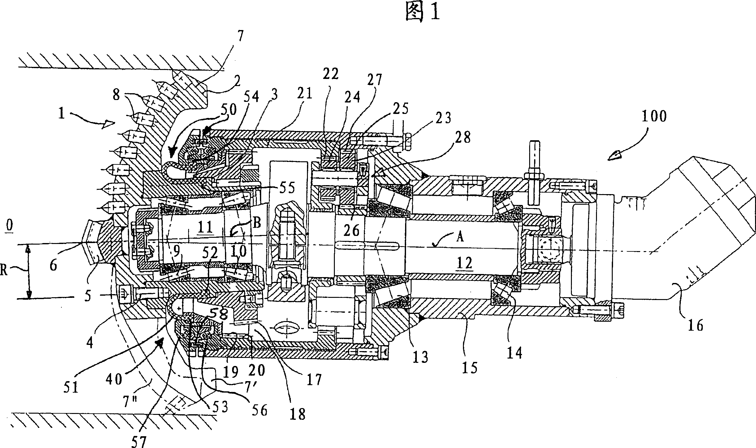
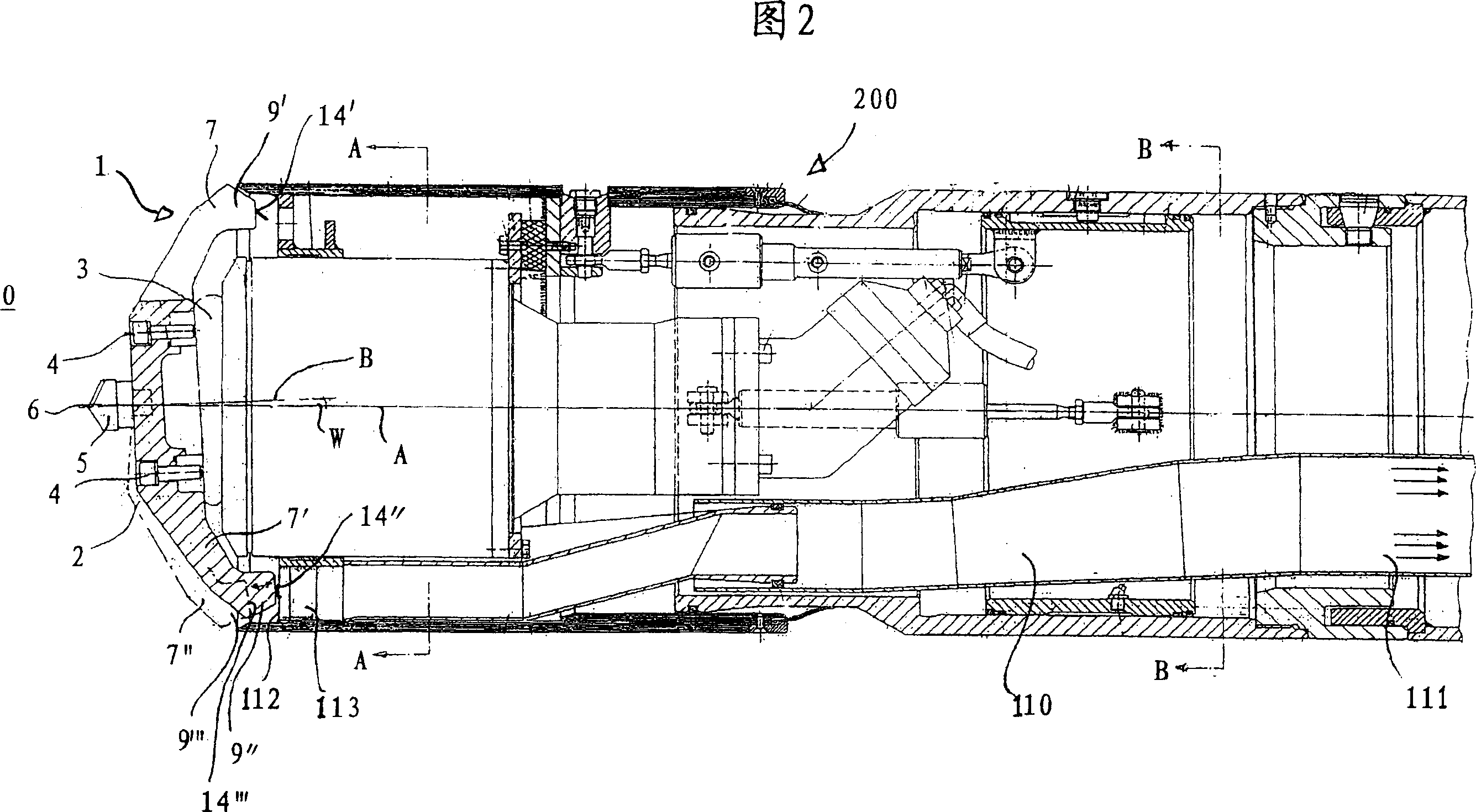
[0036] The device, indicated generally at 100 , comprises a drilling head 1 having a cutter part 30 designed as an excavating disc 2 and a support part 3 . The excavating disc 2 and the support part 3 are fixed to each other with a number of cylindrical screws 4, only one of which can be seen in the figure. Cylindrical screws 4 are uniformly arranged on a pitch circle with a radius R. The tool part 30, which is worn due to the splitting of the drilling head 1 into two parts, can be disassembled on site by loosening the screw 4 after reaching the wear limit and replaced by a new or repaired tool part.

[0037] The excavating disc 2 is equipped with a central cutting edge 5, the tip 6 of which lies on the axis of rotation A of the drilling head. In the illustrated embodiment, the excavating disk 2 has three radially outwardly extending arms 7 , 7 ′, 7 ″, wherein the arm 7 shown at the top in the figure is equipped with a plurality of cutting heads 8 .

[0038] The drilling hea...


PUM


Abstract

Disclosed is a device for advancing drillings in the ground, comprising a rotatably driven main shaft (12) that is provided with a shaft cog (11), the axis (B) of which forms a sharp angle (w) along with the axis (A) of the main shaft (12), and an ear-type head (1) that is rotatably mounted about the axis (B) of the shaft cog (11) and is provided with a peripheral area (18) which runs along an opposite peripheral area (19). The inventive opposite peripheral area (19) can be made to rotate.

Description

technical field [0001] The invention relates to a device for driving a hole in the ground, comprising a rotatably driven main shaft having a journal whose axis forms an acute angle with the axis of the main shaft; The shaft is rotatably mounted and has a peripheral region that rolls on a corresponding peripheral region. Background technique [0002] Such a device is known from DE 4332113 A1. [0003] For horizontal holes with a diameter of about 150 mm to 1300 mm in particular, but also vertical holes in the ground, a drilling device is used in which a rotary drive shaft is rotatably supported in a casing, in which A drilling head is arranged on the end facing the working face wall or the bottom of the hole. [0004] The drilling head is made differently according to the conditions of the ground in which the hole is to be drilled. Difficulties therefore frequently arise when the conditions of the soil to be removed vary over the length of the borehole. Rock drilling bits...

Claims


Application Information

Patent Timeline
Patent Type & Authority Patents(China)
IPC IPC(8): E21B4/00E21B4/16E21B10/08E21D9/11
CPCE21B10/083E21B4/16E21B10/086E21B4/006E21D9/113
Inventor 米夏埃尔·莫尔曼
Owner AKER WIRTH
Learn More