
Displacement sensor with single grating

A technology of displacement sensor and single grating, applied in the field of sensors, can solve the problems of high cost, complex optical path and circuit, and lack of popularization and promotion, and achieve the effects of wide application range, low cost, and convenient installation and debugging

Inactive Publication Date: 2007-10-10
SHANXI UNIV
View PDF4 Cites 0 Cited by
  • Summary
  • Abstract
  • Description
  • Claims
  • Application Information

AI Technical Summary

Problems solved by technology

The optical path and circuit of these methods are relatively complicated, and the installation and matching dimensions between the gratings are strictly required. It is necessary to ensure that the grid lines of the main grating and the indicator grating maintain a fixed small angle, and a suitable small distance must be maintained between the two grating surfaces. When measuring, there must be multiple photosensitive probes moving together with the indicating grating
If you want to make it very precise, its cost must be high, so this measurement method has not been popularized for a long time

Method used


Image

  • Displacement sensor with single grating
  • Displacement sensor with single grating
  • Displacement sensor with single grating

Examples


Embodiment Construction

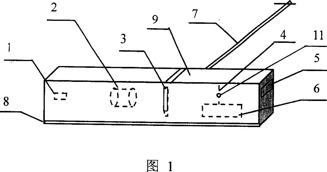
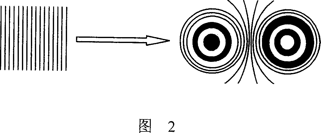
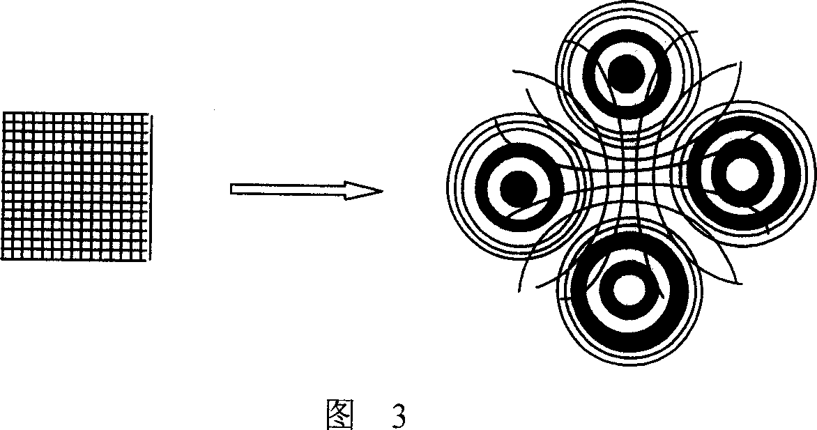
[0022] A single grating displacement sensor of the present invention, as shown in Figure 1: an optical lens 2 is set between the light source 1 and the grating 3, the extended light of the light source 1 is focused on the grating 3 through the optical lens 2, and then projected on the light screen 4 superior. A photosensitive probe 11 is arranged on the light screen 4 and connected to the circuit 6 and the display system 5 . The light source 1 of the sensor is a laser pointer, the optical lens 2 is a common convex lens, the light screen 4 is frosted glass, they are fixed on the base 8, the grating 3 is a transmissive one-dimensional sinusoidal grating, and a horizontal one-dimensional slide bar 7 are connected into one body, and the photosensitive probe 11 adopts a photosensitive diode. The optical lens focuses an expanded light on the grating and adjusts it appropriately. After the grating is processed by this light, the grid lines of the grating are enlarged and deformed, s...


PUM


Abstract

A displacement transducer of single grating consisting of light source and grating is featured as setting optical lens between light source and grating, focusing expansion light of source on grating through optical lens and projecting it or reflecting it on light screen for carrying out photoelectrical count. It can be used to measure the amount of linear displacement or angle displacement.

Description

technical field [0001] The invention relates to a sensor, in particular to a precision displacement sensor with light conversion single grating. The sensor can be used in earthquake monitoring, mechanical processing, aerospace measurement and control, weight measurement, medical monitoring, physical instruments and other fields. Background technique [0002] Most grating displacement sensors adopt the Moiré fringe counting method generated by double gratings, or the circuit subdivision method based on the Moiré fringe counting. The optical path and circuit of these methods are relatively complicated, and the installation and matching dimensions between the gratings are strictly required. It is necessary to ensure that the fixed small angle is maintained between the grid lines of the main grating and the indicating grating, and a suitable small distance must be maintained between the two grating surfaces. When measuring, there must be multiple photosensitive probes moving to...

Claims


Application Information

Patent Timeline
Patent Type & Authority Patents(China)
IPC IPC(8): G01D5/38G01D5/26G01B11/02
Inventor 武少文董有尔杨保东李秀平
Owner SHANXI UNIV
Learn More