Apparatus for cutting rumble strips in a road surface

a technology for rumble strips and apparatuses, applied in cutting machines, roads, construction, etc., can solve the problems of reducing the effectiveness of rumble strips, rolling drums used on asphaltic roads, etc., and achieve the effect of easy removal of debris, convenient observation, and reduced areas

Inactive Publication Date: 2008-09-16
DUSTROL
View PDF18 Cites 7 Cited by
  • Summary
  • Abstract
  • Description
  • Claims
  • Application Information

AI Technical Summary

Benefits of technology

[0012]The rumble strip depressions of the present invention have bottoms that curve along both perpendicular axes, in contrast to conventional rumble strips that curve upwardly along only one axis. The resulting forward and rearward side walls curve in a horizontal plane and, when painted with traffic paint or another light reflective coating, is more readily observable because light from vehicle headlights is reflected in multiple directions. The curved nature of the bottoms of the ...

Problems solved by technology

Roller drums, however, can only be used on asphaltic roads, and the impressed depressions may tend to rebound over a period of time, thereby reducing the effectiveness of the rumble strips.
Using forms to shape the depressions is of limited applicability because the forms can only be used with wet concrete.
The vertically extending lateral walls in conventional rumble strip depressions can cause several problems.
First, when a vehicle drifts off the travel lanes and onto a rumble strip positioned on the road shoulder, the vertical lateral walls cause the tires to suddenly drop laterally from the road surface into the rumble strip depression.
This abrupt movement may pull the vehicle even further onto the shoulder and may momentarily distract the vehicle driver.
O...

Method used


Image

  • Apparatus for cutting rumble strips in a road surface
  • Apparatus for cutting rumble strips in a road surface
  • Apparatus for cutting rumble strips in a road surface

Examples


Embodiment Construction

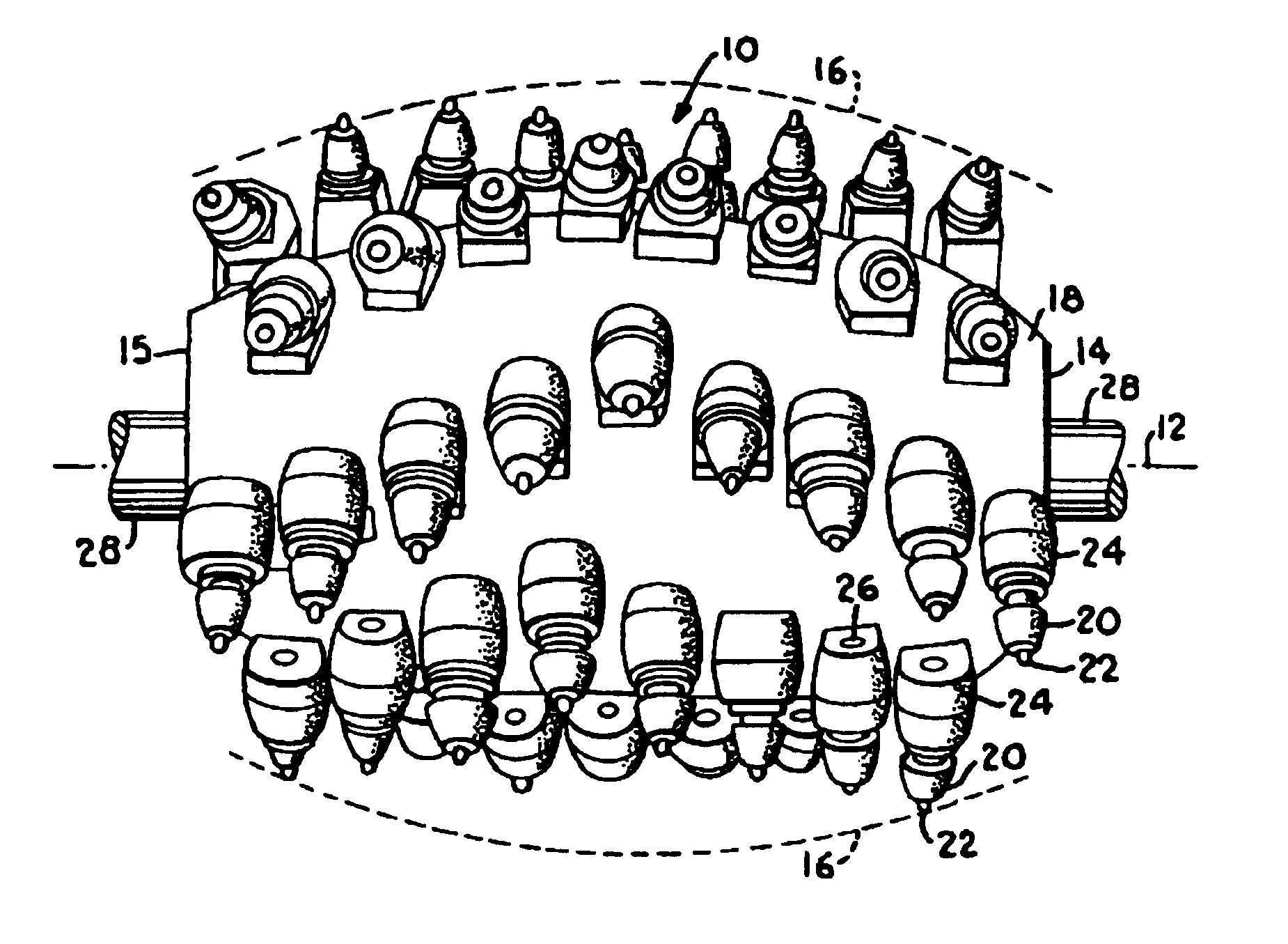
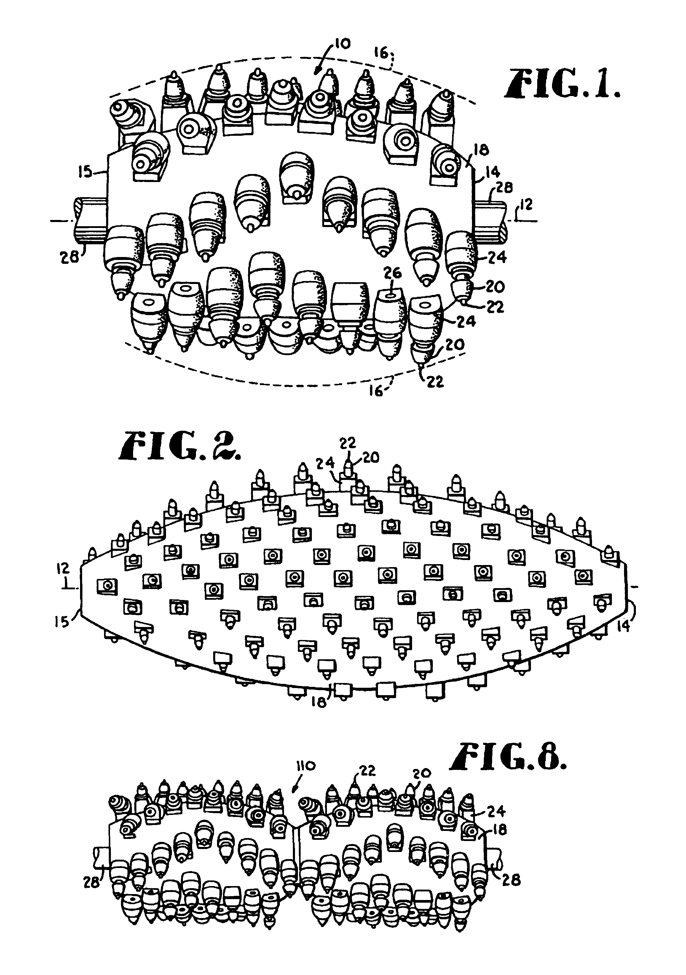
[0022]Referring now to the drawings in greater detail, and initially to FIG. 1, a cutting head used to mill rumble strip depressions in accordance with the present invention is represented broadly by the numeral 10. The cutting head 10 is designed to be rotated about a center rotational axis 12 as it is moved up and down to mill away portions of a road surface to form the rumble strip depressions in the road.

[0023]The cutting head 10 has a preselected length along its rotational axis 12 and a transverse diameter that varies along the length of the rotational axis 12. As used herein, the transverse diameter is understood to be taken in a plane perpendicular to the rotational axis 12. In the preferred embodiment, the smallest transverse diameter is at opposite ends 14 and 15 of the cutting head 10 and the greatest transverse diameter is midway between the ends 14 and 15. It will be appreciated that the areas of smallest and greatest transverse diameter can be shifted along the axis 12...


PUM


Abstract

A cutting head is provided for milling rumble strip depressions in a road surface. The cutting head has a center rotational axis and a transverse diameter that varies along the length of the rotational axis so that an outer cutting surface of the cutting head defines a plane curve, such as an ellipsoid with truncated ends. The cutting head is mounted on a milling machine and rotated about the rotational axis as it is moved alternately up and down into the road surface. As the milling machine moves down the road, the movement of the cutting head creates spaced apart rumble strip depressions in the road. Because of the elliptical configuration of the cutting head cutting surface, the dimensions of the depressions can be varied along both the forward and lateral axes by simply varying the depth of cut. The curved profile of the cutting head along the rotational axis creates rumble strip depressions that avoid the sharp ninety degree corners and vertical side walls found in conventional rumble strips.

Description

CROSS-REFERENCE TO RELATED APPLICATIONS[0001]This application claims priority from provisional application Ser. No. 60 / 333,897 filed Nov. 28, 2001 and is a continuation-in-part of application Ser. No. 09 / 783,418 filed Feb. 14, 2001 now U.S. Pat. No. 6,454,490.BACKGROUND OF THE INVENTION[0002]The present invention relates generally to road safety devices and, more particularly, to rumble strips and methods and apparatus for forming same.[0003]Depressions, commonly referred to as rumble strips or sonic nap alert patterns (SNAPS), are formed in the surfaces of roads to alert drivers when their vehicles have drifted out of the travel lane of the road or when the vehicle is approaching a dangerous portion of road, such as a stop sign or toll booth. Rumble strip depressions are typically either uniformly spaced apart or are placed in spaced apart groupings in what is known as a skip pattern. Although there is no uniform standard for rumble strips, many highway departments require a five i...

Claims


Application Information

Patent Timeline
IPC IPC(8): E01C23/16
CPCE01C23/0993
Inventor MURPHY, TIM L.
Owner DUSTROL
Why Eureka
Try Eureka