
Bus-to-bus bridge in computer system, with fast burst memory range

a computer system and bus-to-bus technology, applied in the field of computer systems, can solve problems such as destroying the benefits of superpipelining on the p6 bus

Inactive Publication Date: 2003-02-04
HEWLETT-PACKARD ENTERPRISE DEV LP
View PDF8 Cites 44 Cited by
  • Summary
  • Abstract
  • Description
  • Claims
  • Application Information

AI Technical Summary

Benefits of technology

It is therefore one object of the present invention to provide an improved way of handling fast burst transactions on a bus in a computer system.
It is another object of the present invention to provide an improved computer system having enhanced performance when making accesses to devices on an expansion bus, using a bridge between a processor bus and an expansion bus.
It is a further object of the present invention to provide an improved bridge circuit for connecting a processor bus to an expansion bus, particularly one allowing fast burst transactions.

Problems solved by technology

This would destroy the benefits of superpipelining on the P6 bus.

Method used


Image

  • Bus-to-bus bridge in computer system, with fast burst memory range
  • Bus-to-bus bridge in computer system, with fast burst memory range
  • Bus-to-bus bridge in computer system, with fast burst memory range

Examples


Embodiment Construction

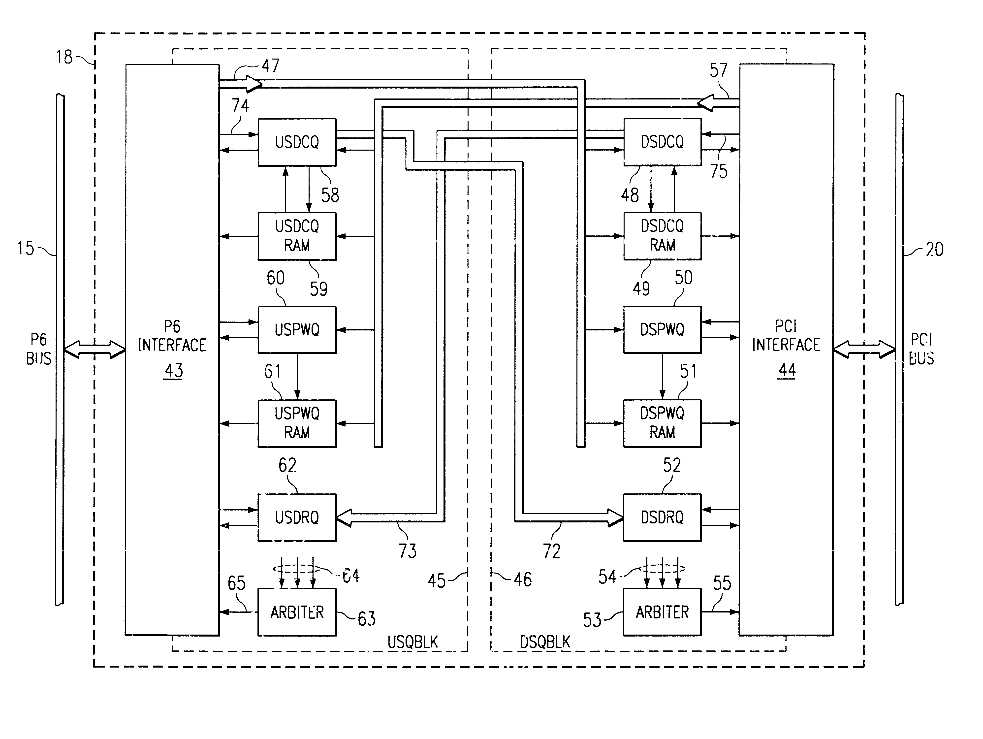
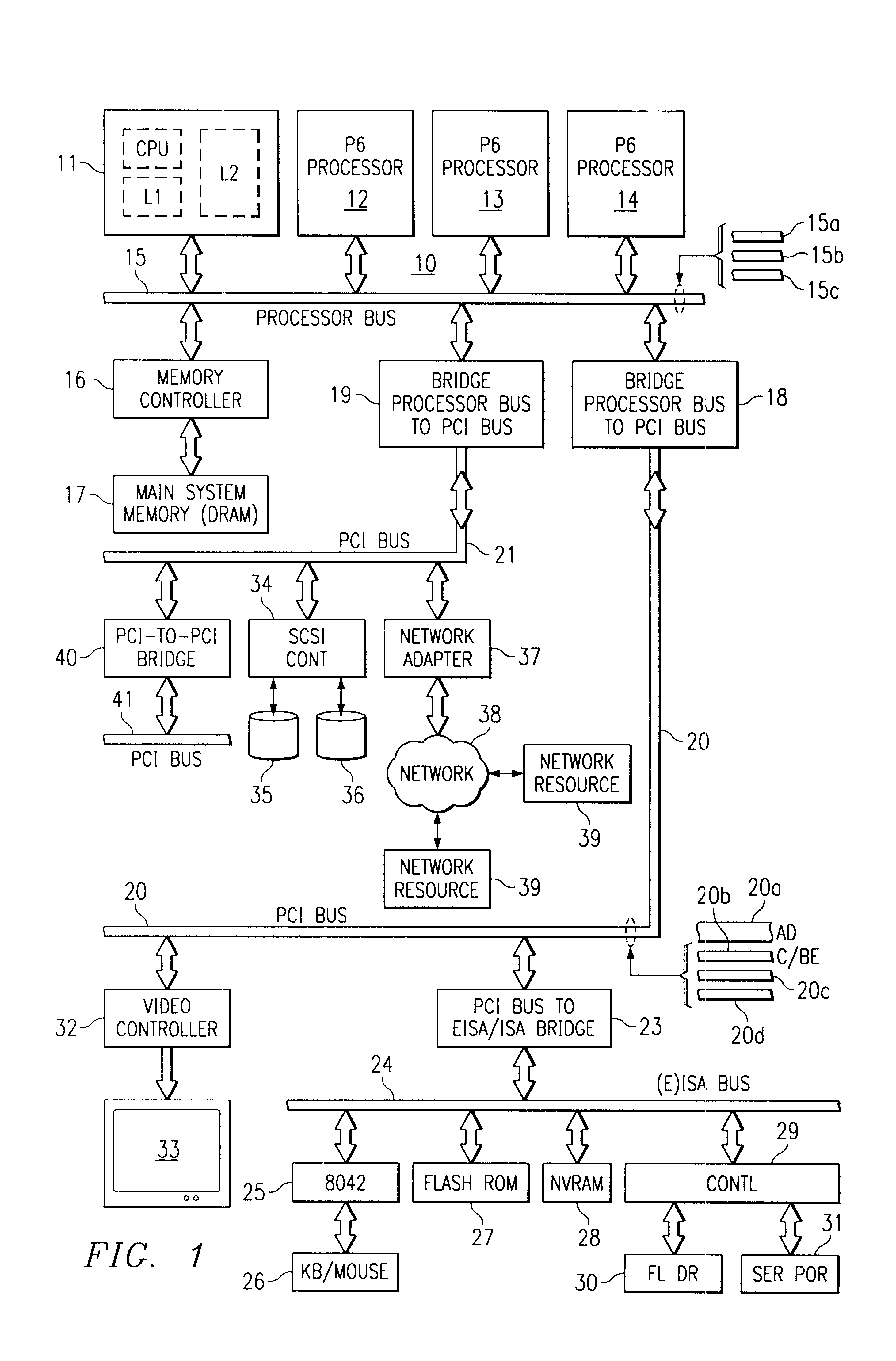
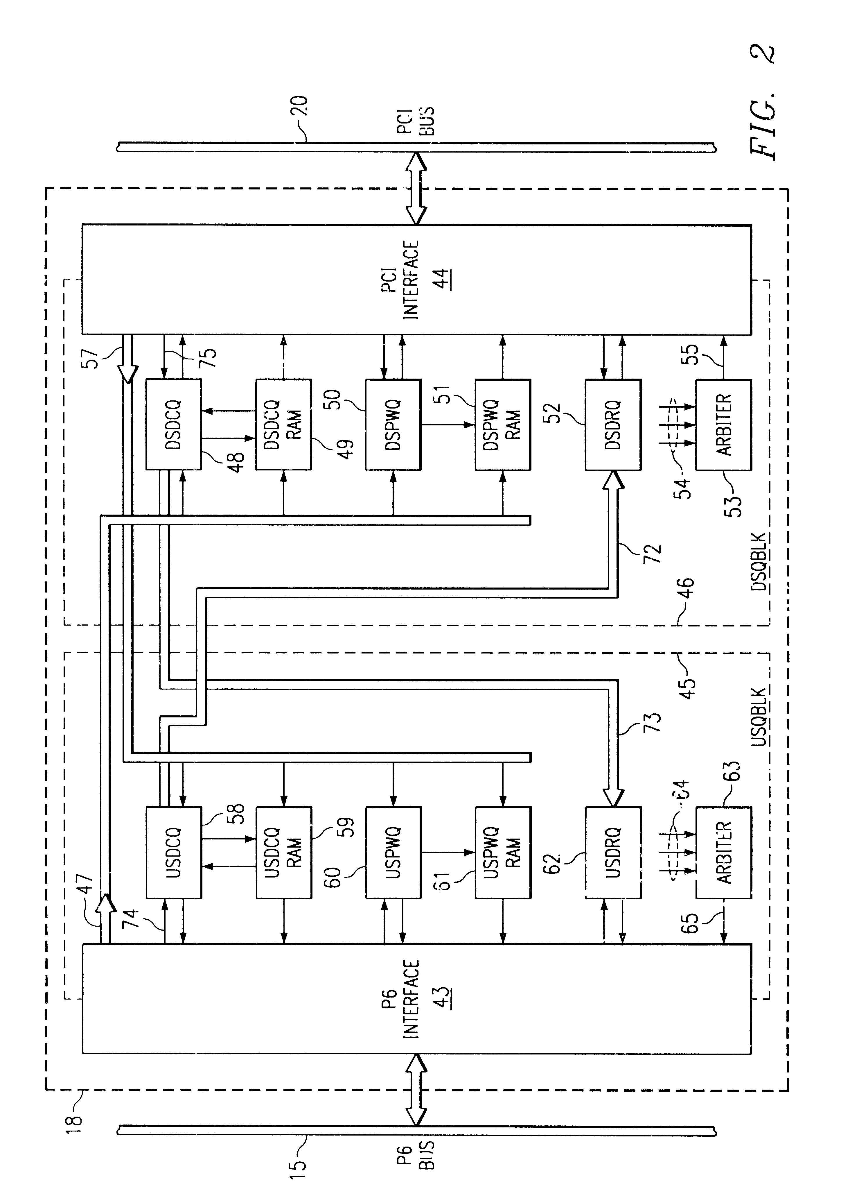
Referring to FIG. 1, a computer system 10 is shown which may use features of the invention, according to one embodiment. The system includes multiple processors 11, 12, 13 and 14 in this example, although the improvements may be used in a single processor environment. The processors are of the type manufactured and sold by Intel Corporation under the trade name PENTIUM PRO, although the processors are also referred to as "P6" devices. The structure and operation of these processors 11, 12, 13, and 14 are described in detail in the above-mentioned Intel publications, as well as in numerous other publications. The processors are connected to a processor bus 15 which is generally of the structure specified by the processor specification, in this case a Pentium Pro specification. The bus 15 operates at a submultiple of the processor clock, so if the processors are 166 MHz or 200 MHz devices, for example, then the bus 15 is operated based on some multiple of the base clock rate. The main...


PUM


Abstract

A computer system has a processor bus under control of the microprocessor itself, and this bus communicates with main memory, providing high-performance access for most cache fill operations. In addition, the system includes one or more expansion buses, preferably of the PCI type in the example embodiment. A host-to-PCI bridge is used for coupling the processor bus to the expansion bus. Other buses may be coupled to the PCI bus via PCI-to-(E) ISA bridges, for example. The host-to-PCI bridge contains queues for posted writes and delayed read requests. All transactions are queued going through the bridge, upstream or downstream. The system bus is superpipelined, in that transactions overlap. A fast burst transactions are allowed between the bridge and main memory, i.e., requests which can be satisfied without deferring or retrying are applied to the system bus without waiting to get a response from the target. A range of addresses (e.g., system memory addresses) is defined to be a fast burst range, and any address in this range is treated differently compared to addresses outside the range. The bridge is programmed, by configuration cycles, to establish this fast burst range, within which it is known that an out-of-order response will not be received. When a transaction reaches a bridge interface from the PCI bus, and it is recognized that the address is within the fast burst range, then the fast burst mode is allowed, and write or read requests can be issued without waiting for the snoop phase, since there is no possibility of defer or retry.

Description

BACKGROUND OF THE INVENTIONThis invention relates to computer systems, and more particularly to a memory access protocol for a computer system bus which uses a bridge between a processor bus and a standardized system bus.Computer systems of the PC type usually employ a so-called expansion bus to handle various data transfers and transactions related to I / O and disk access. The expansion bus is separate from the system bus or from the bus to which the processor is connected, but is coupled to the system bus by a bridge circuit.For some time, all PC's employed the ISA (Industry Standard Architecture) expansion bus, which was an 8-MHz, 16-bit device (actually clocked at 8.33 MHz). Using two cycles of the bus clock to complete a transfer, the theoretical maximum transfer rate was 8.33 MBytes / sec. Next, the EISA (Extension to ISA) bus was widely used, this being a 32-bit bus clocked at 8MHz, allowing burst transfers at one per clock cycle, so the theoretical maximum was increased to 33-M...

Claims


Application Information

Patent Timeline
IPC IPC(8): G06F13/40
CPCG06F13/4027G06F13/4059
Inventor ELKHOURY, BASSAMPETTEY, CHRISTOPHER J.RILEY, DWIGHTSEEMAN, THOMAS R.HAUSAUER, BRIAN S.
Owner HEWLETT-PACKARD ENTERPRISE DEV LP
Learn More