
Method and apparatus for testing LCD panel array prior to shorting bar removal

a technology of liquid crystal display and panel array, which is applied in the direction of optical apparatus testing, television system, instruments, etc., can solve the problems of pixel short circuit and inactive pixels

Inactive Publication Date: 2002-09-17
PHOTON DYNAMICS
View PDF11 Cites 51 Cited by
  • Summary
  • Abstract
  • Description
  • Claims
  • Application Information

AI Technical Summary

Benefits of technology

According to the invention, an LCD panel or the like is tested for open circuit defects and pixel defects after preliminary short circuit testing is complete. According to one aspect of the invention, the panel undergoes open circuit and pixel testing by exposing the panel to test signals at the contacts of each respective shorting bar. The resulting display pattern then is imaged and compared to an expected display pattern to detect panel defects.

Problems solved by technology

Any pixels that become inactive result from a pixel short circuit.

Method used


Image

  • Method and apparatus for testing LCD panel array prior to shorting bar removal
  • Method and apparatus for testing LCD panel array prior to shorting bar removal
  • Method and apparatus for testing LCD panel array prior to shorting bar removal

Examples


Embodiment Construction

Panel Configuration

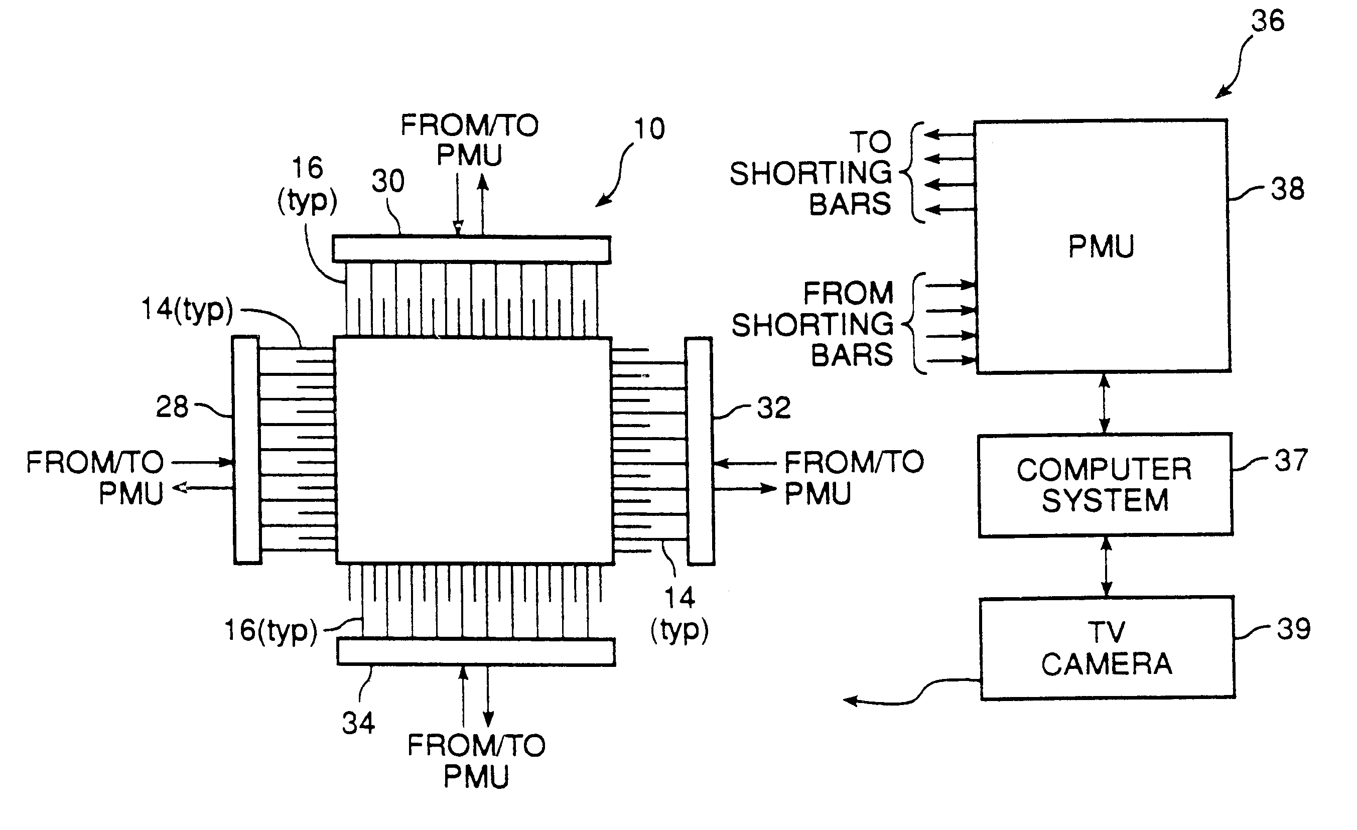
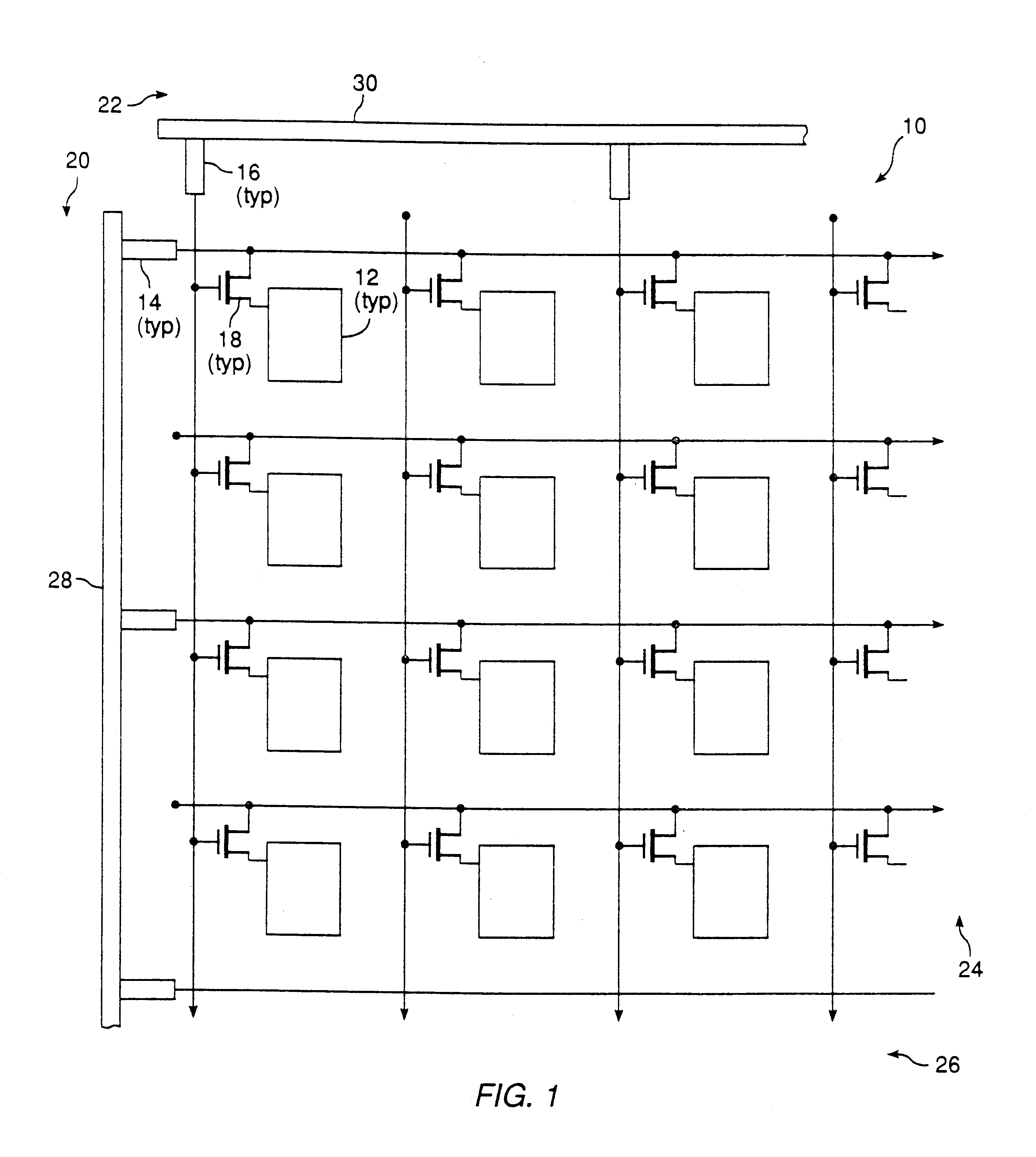
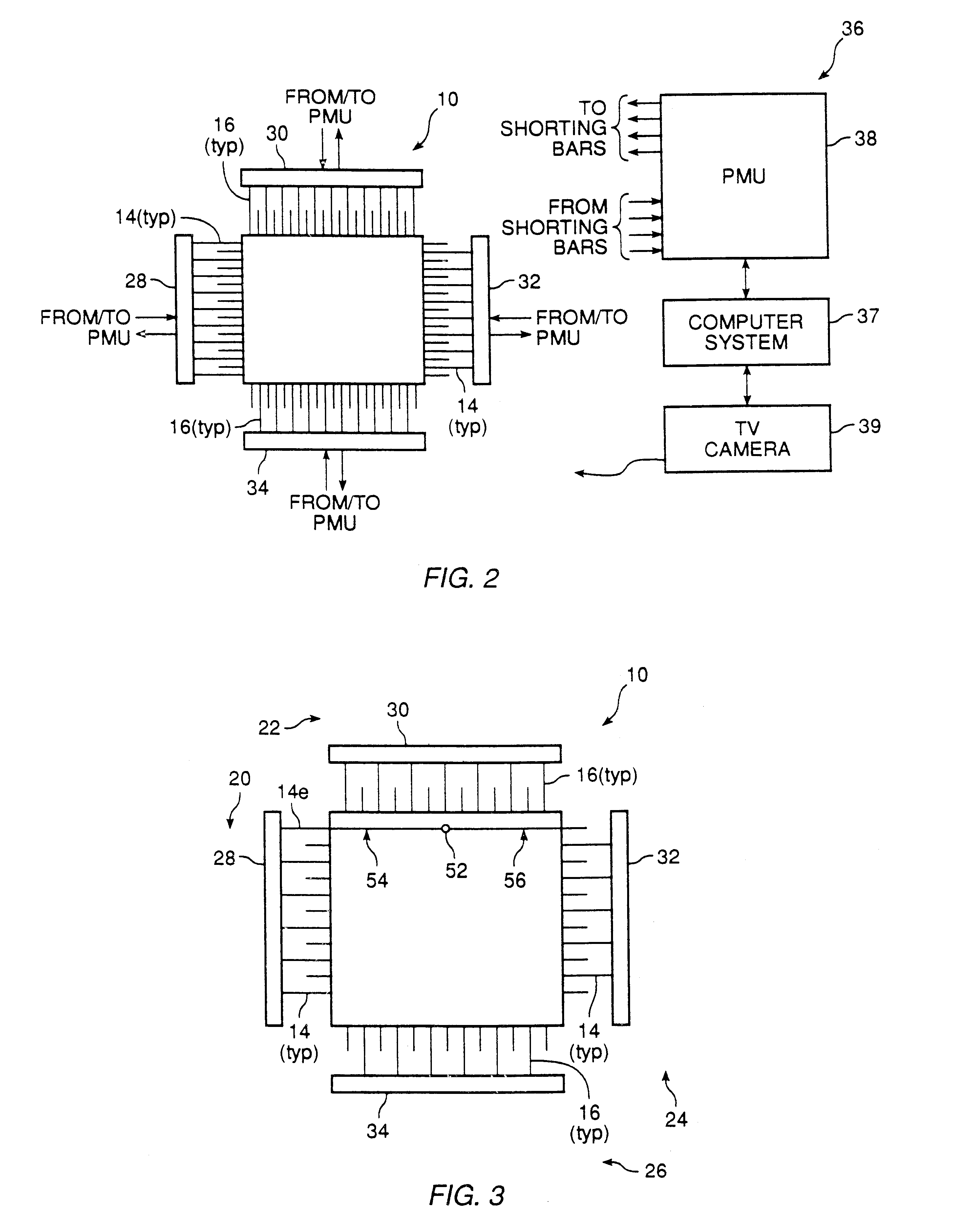
Referring to FIG. 1, a section of an LCD panel 10 is shown including several pixels 12. Associated with each pixel 12 is a drive line 14, a gate line 16, and a drive element 18, as previously described. For an interdigitated panel (shown), every other drive line is terminated along one panel boundary 20, while the other drive lines are terminated along the opposite, but parallel, boundary 24 (see FIG. 2). Similarly, every other gate line 16 is terminated along one panel boundary 22 adjacent and generally orthogonal to the drive line panel boundaries 20, 24, while the other gate lines 16 are terminated along the opposite panel boundary 26.

During final testing of the LCD panel 10, the electro-static discharge shorting bars are present. As shown in FIGS. 1-3, there are four shorting bars 28, 30, 32, 34 for an interdigitated panel, one at each edge of the panel 10. Bar 28 shorts the drive lines 14 terminating at edge 20. Bar 30 shorts the gate lines 16 terminating at ...


PUM

PropertyMeasurementUnit
timeaaaaaaaaaa
optical sensingaaaaaaaaaa
voltageaaaaaaaaaa

Abstract

Final testing of an LCD panel or the like is performed after preliminary testing for short circuit defects. During final testing, the panel is exposed to signals at the shorting bars and the resulting display pattern is imaged. The resulting image data then is processed at a computer system to determine whether the resulting display pattern differs from an expected display pattern. If differences are present then an open circuit or pixel defect is present. The applied test signals and the pattern or differences determine the type of defect present. For an open circuit defect along a gate line, a partial row (column) of the resulting display pattern does not activate. For an open circuit along a drive line, a partial column (row) of the resulting display does not activate. Pixel shorts are identified by applying test signals to the shorting bars during a first test cycle, then imaging the display during a second test cycle after at least one of the test signals is removed. Pixels which remain active that should be inactive have short circuit defects.

Description

CROSS REFERENCE TO RELATED APPLICATIONThis invention is related to commonly-assigned U.S. patent application Ser. No. 07 / 557,257, filed July 24, 1990 of the same inventor for METHOD AND APPARATUS FOR TESTING AN LCD PANEL ARRAY USING A MAGNETIC FIELD SENSOR.BACKGROUND OF THE INVENTIONThis invention relates to testing of liquid crystal display (LCD) panel arrays, and more particularly to a method and apparatus for testing LCD panel arrays for open circuit and pixel defects by applying test signals to panel shorting bars.LCD panels typically are formed with a liquid crystal material sandwiched between an active plate and a ground plate. Polarizers, colorizing filters and spacers also are included between the plates. During fabrication, many active .[.plates.]. .Iadd.panels .Iaddend.may be formed on a single glass plate. In each area of the glass plate which is to form an active .[.plate,.]. .Iadd.panel, .Iaddend.drive lines, gate lines and drive elements are formed. Typically, thin-fil...

Claims


Application Information

Patent Timeline
Patent Type & Authority Patents(United States)
IPC IPC(8): G01R31/316G01R31/28G06F11/24G09G3/00G01M11/00G01D18/00G01N21/88G01N21/93G01N21/956G02F1/13H01L29/78H01L29/786
CPCG01R31/316G06F11/24G09G3/006Y10S345/904
Inventor HENLEY, FRANCOIS J.BARTON, STEPHEN
Owner PHOTON DYNAMICS
Learn More