
Magnification setting apparatus for image forming apparatus

a technology of image forming apparatus and magnification setting, which is applied in the direction of electrographic process apparatus, instruments, optics, etc., can solve the problems of unskilled operators not knowing the fixed magnification, unfavorable operation, and inability to set the magnification at all, so as to simplify the operation

Inactive Publication Date:
View PDF18 Cites 16 Cited by
  • Summary
  • Abstract
  • Description
  • Claims
  • Application Information

AI Technical Summary

Benefits of technology

To solve the problems described above, a first object of the invention is to simplify an operation for setting a magnification. A further object of the invention is to provide for a magnification setting apparatus which allows setting of not only a fixed magnification but also an optional magnification by means of a key for setting a magnification.
Further, with respect to setting of a fixed magnification, by returning to an immediately precedent fixed magnification which is passed within a predetermined period of time, it is possible to set a fixed magnification easily and to set an optional magnification easily and accurately.

Problems solved by technology

However, during setting of a magnification described above, although a skilled operator is capable of easily manipulating, an unskilled operator can not very often understand at all what a fixed magnification is.
That is, even though an unskilled operator can understand that the original size is B4, he can not understand at all whether to set a magnification by manipulating a fixed magnification key or by manipulating a zoom key for the purpose of form an image on an A4 paper.
In addition, where a fixed magnification is to be set by means of a zoom key, an unskilled operator does not know the fixed magnification to be set, often ending up in setting a wrong magnification.
To avoid this, an unskilled operator must to refer to a comparison chart while setting a magnification, which is very bothersome.
Further, provision of a fixed magnification key and a zoom key separately from each other as described above simply increases the number of setting keys to be used by an operator so that it is very hard for the operator to understand which key to manipulate to easily set a desired magnification, which forces the operator a bothersome operation.
In addition, since the operator must set a magnification while looking at the comparison chart described above, without the comparison chart, the operator may rely on his own intuition when setting a wrong magnification and end up in making an undesired copy.
However, a user must store such magnifications in advance, and therefore, an inexperienced user feels awkward toward the increased number of the setting keys and finds setting of a magnification very pressurizing.
However, in the case where there are a number of keys, such as keys corresponding to respective fixed magnification keys, a zoom key, and a special fixed magnification key as described above, provided for providing such a display described above, due to a restriction to a space on an operation panel for providing a number of keys, printing or displaying with very small letters can not avoided in reality.
Such a display is very hard to look at, making reference to the display very rare.
Further, when combinations of optimal conditions for all originals and all paper sizes corresponding to respective fixed magnifications are displayed, together with a problem that a small display is forced as described above, searching of a proper condition requires a bothersome operation.
In addition, arrangement of a number of keys, such as a zoom key, fixed magnification keys and magnification memory keys for often-used magnifications, on an operation gives a stronger impression to a user, and the user tends to feel that an operation is bothersome.
Further, in the case where a fixed magnification is to be or a magnification which is close to the fixed magnification is to be set by means of a zoom key, although an operator is very familiar with the very magnification as described above, when the operator is inexperienced, the operator can not easily understand a magnification to be set and setting is very difficult for the operator.

Method used


Image

  • Magnification setting apparatus for image forming apparatus
  • Magnification setting apparatus for image forming apparatus
  • Magnification setting apparatus for image forming apparatus

Examples


first embodiment

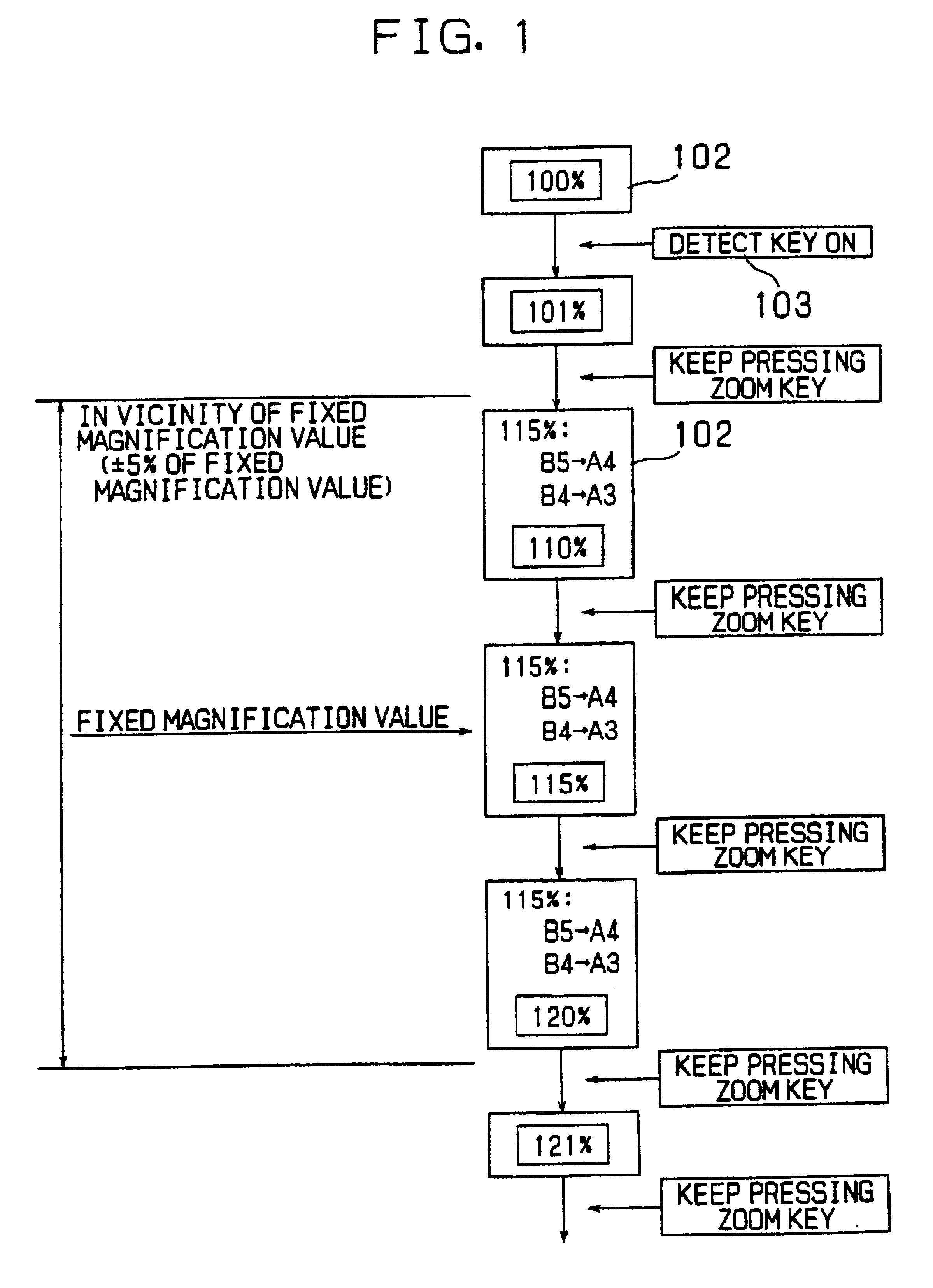
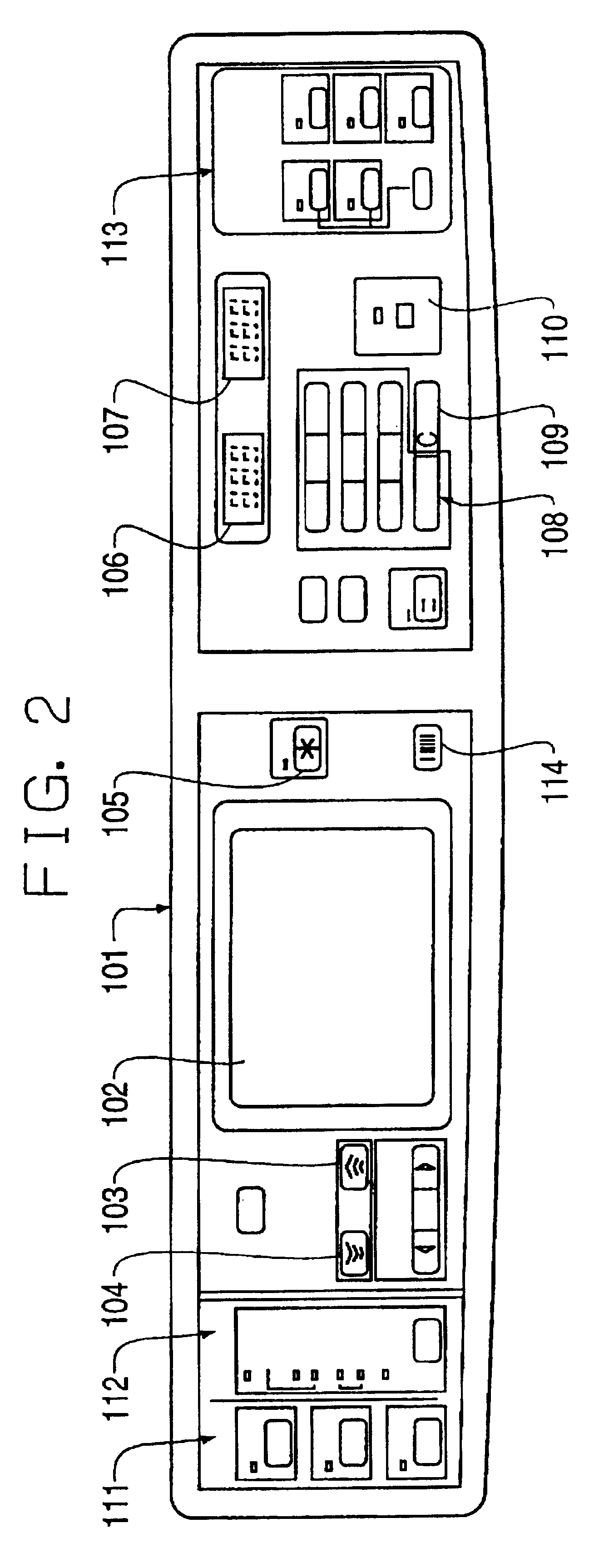
FIG. 1 is a view showing original and paper sizes in an optimal condition in the vicinity of a fixed magnification are displayed together with a set magnification as a sub message, in a magnification setting apparatus for use in an image forming apparatus according to the invention. FIG. 2 is a plan view showing one example of an operation panel with which an operator sets a magnification according to the invention. FIG. 3 is a block diagram showing a circuitry structure of a control portion of a scan panel portion of FIG. 2, including controlling of an image forming operation in the image forming apparatus. FIG. 4 is a cross-sectional view showing an outline of an inner structure of a digital copying machine which comprises the operation panel of FIG. 2. FIG. 5 is an essential cross-sectional view showing one example of a copying machine in other image forming apparatus in which an image exposure portion focuses an analog image, i.e., an original image directly onto a photosensitiv...

second embodiment

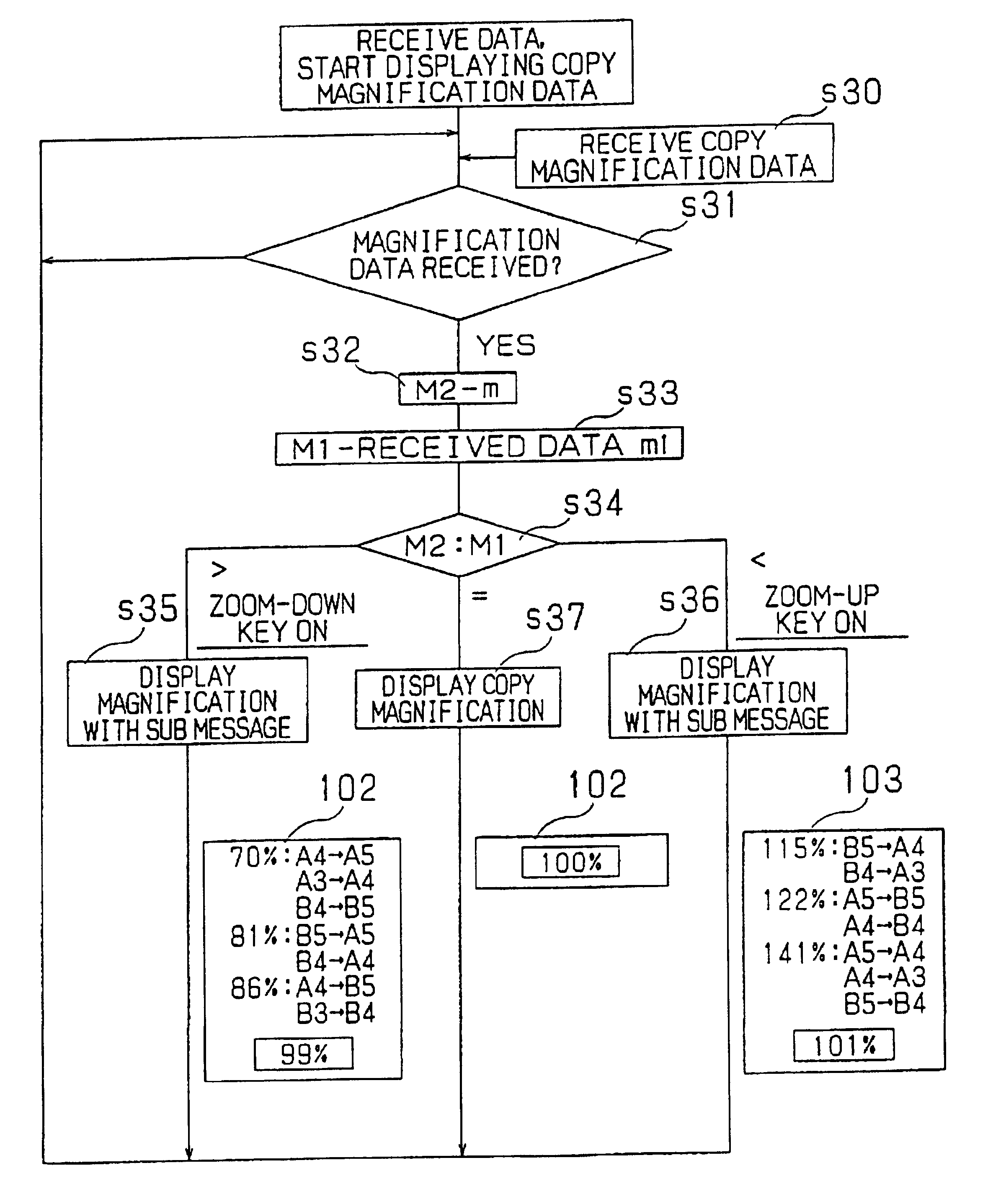
Further, the various fixed magnifications of the zoom up or down direction may be displayed together with sub messages all at once. In this case, with the initial value of 100%, in response to an operation of the zoom up key 103, together with the fixed magnifications of 122% and 141%, in accordance with these fixed magnifications, sub messages "A4.fwdarw.B4" and "A4.fwdarw.A3" are displayed all at once. On the other hand, in response to an operation of the zoom down key 104, with the initial value of 100%, together with the fixed magnifications of 86% and 70%, in accordance with these fixed magnifications, sub messages "A4.fwdarw.B5" and "A4.fwdarw.A5" are displayed all at once.

In this manner, by displaying the fixed magnifications and the sub messages in accordance with the set original size, a desired magnification can be easily recognized and set. Since a paper size allowing copying with the set original size is specified, even though understanding of a desired magnification fa...

third embodiment

When sub messages are displayed all at once which are combinations of fixed magnifications and paper sizes as described above as the third embodiment, erasing of fixed magnifications which are passed in the zoom up or down direction may be combined with distinguishing of the next fixed magnification and the other fixed magnifications. This further narrows down combinations for sub messages, and hence, makes setting of a magnification even more accurate and easy.

Now, as described in relation to the first embodiment, during setting of a magnification and zooming up or down, when the magnification is changed very quickly, a mistake may occur during setting of the magnification. A description will be given on an actual example for slowing down shifting of the magnification in the vicinity of fixed magnifications to deal with this.

In this case, a shifting of the magnification is slowed down in the vicinity of a fixed magnification, it is possible to accurately set the magnification. On t...


PUM


Abstract

When zoom keys for changing a magnification by a predetermined unit each time, not only setting of a fixed magnification is bothersome, but also setting a magnification in the vicinity of the fixed magnification is very troublesome. A zoom up key and a zoom down key for changing a magnification by a predetermined unit, e.g., 1%, each time to set to a desired magnification are provided. By operating either one of the keys, a set magnification is zoomed up or down, while displaying that condition in an LCD display which serves as a display portion. While the set magnification shifts, when the set magnification becomes a fixed magnification or a magnification close to the same, a sub message as well is displayed which indicates an optimal combination of original and paper sizes with which processing at that fixed magnification is possible. Referring to the displayed sub message, the desired magnification is set by operating the zoom up key or the zoom down key.

Description

BACKGROUND OF THE INVENTION1. Field of the InventionThe present invention relates to setting of an optional magnification of image formation in an image forming process which is performed by an image forming apparatus.2. Description of the Related ArtIn an image forming apparatus, especially in a copying machine, a laser printer and the like which utilize electrophotographic method, a photosensitive material which is a recording medium is uniformly electrified so that after uniform electrification, reflected light from an original or laser light which is driven in accordance with image information irradiates and forms an electrostatic image corresponding to the image on a surface of the photosensitive material, and a developing agent is used to develop the electrostatic image and obtain a visible image. The developed image is transferred onto a sheet of paper which is transported appropriately and the sheet of paper is fed into a fixing apparatus so that a toner image transferred on...

Claims


Application Information

Patent Timeline
Patent Type & Authority Patents(United States)
IPC IPC(8): G03G15/00G03G21/00
CPCG03G15/5016G03G15/502
Inventor ISHIKURA, KAORUOKAMOTO, YUJI
Learn More