Tablet-based commissioning tool for addressable lighting

a technology of illumination system and tabletop, applied in the field of illumination system, can solve the problems of time-consuming process, inability to know exactly where in the structure each of the components are, and inability to identify all of the light sources one by one in this manner, and achieve the effect of efficient and fast manner

Active Publication Date: 2018-06-12
SIGNIFY HLDG BV
View PDF26 Cites 2 Cited by
  • Summary
  • Abstract
  • Description
  • Claims
  • Application Information

AI Technical Summary

Benefits of technology

[0010]Embodiments of the present invention are based on several recognitions. First of all, having the controllable devices transmit their identification signals has been recognized to allow automatic discovery of the controllable devices that have been installed in the structure. Second, providing a user with a portable electronic device that is configured to display icons for the controllable devices that have been discovered and that allows the user to control the controllable devices to identify themselves to the user enables the user to map the discovered controllable devices by assigning their icons to be displayed at certain locations on a map of the structure. In this manner, a computer-readable (i.e. electronic) location information is obtained where a map of the structure is populated with indications of the locations of the controllable devices within the structure. Such a populated map may then be used by a commissioning engineer, e.g. by means of a central controller, to control the installed system by e.g. configuring one or more operating parameters of the controllable devices, depending on their location within the structure.
[0012]In an embodiment, the method may further comprise providing information indicative of the location for the first icon as selected by the user to a central controller. This could be done for all of the icons for which the user selected appropriate locations on the map displayed on the display, i.e. for all of the devices for which the user was able to make the connections between the device ID and the corresponding location of the device in the structure. Providing to the central controller information indicating locations of the individual devices in the structure enables the central controller to configure the devices by e.g. setting or changing one or more operating parameters of the devices.
[0013]In an embodiment, the installed system may further comprise a control device and the method may further comprise wirelessly receiving a signal indicative of the control device being actuated, e.g., a signal indicative of the user actuating the control device in the structure, detecting a third user input indicative of a selection by the user of one or more icons of the plurality of icons displayed on the display, including at least the first icon, the one or more icons corresponding to one or more devices to be controlled by the control device, and binding (or linking) the one or more devices to the control device so that the one or more devices are controllable by the control device. This embodiment allows the user to continue the commissioning process by binding the control device(s) to one or more devices to be controlled.
[0014]In one further embodiment, the method may also comprise detecting a fourth user input indicative of a selection by the user of a location on the displayed map for a control icon corresponding to the control device, and displaying the control icon on the map at the location selected by the user. This embodiment may also, optionally, include the step of displaying on the display the control icon corresponding to the control device prior to detecting the fourth user input (i.e., a control icon is first displayed somewhere on the display, for the user, before the user can indicate where on the map the icon should be displayed). These embodiments advantageously allow placing a control icon associated with the control device of the system in a location on the displayed map that would be intuitive for the user, e.g. in a location corresponding to the physical location of the control device in the structure, thereby enabling the user to carry out the commissioning in a more efficient and faster manner.
[0015]In an embodiment, the method may further comprise providing on the display a visual indication of the one or more devices that have been bound to the control device. This embodiment provides the advantage of making the information regarding which controllable device(s) is (are) controlled by which control device(s) available to the user, thereby further assisting the user in carrying out the commissioning process because the user may easily find the necessary control device(s) to control the controllable device(s).
[0017]In an embodiment, the location for the first icon on the displayed map may comprise one predefined location of a plurality of predefined selectable locations. This embodiment assists the user in positioning the icon for the first device in the appropriate place on the map by providing to the user predefined locations for the plurality of the devices from which the user can make a selection.

Problems solved by technology

However, at that point, it is not known where exactly within the structure each of the components is actually installed.
One problem with such an approach is that, with a large lighting system, identifying all of the light sources one by one in this manner could be a very lengthy process.
Not only can this process be, again, time consuming, particularly with large lighting systems, but it is also error prone both on the part of the installer sticking the barcodes in the correct places on the print out and on the part of the commissioning engineer transferring this information into the electronic format.

Method used


Image

  • Tablet-based commissioning tool for addressable lighting
  • Tablet-based commissioning tool for addressable lighting
  • Tablet-based commissioning tool for addressable lighting

Examples


Embodiment Construction

[0032]In the following description, numerous specific details are set forth to provide a more thorough understanding of the present invention. However, it will be apparent to one of skill in the art that the present invention may be practiced without one or more of these specific details. In other instances, well-known features have not been described in order to avoid obscuring the present invention.

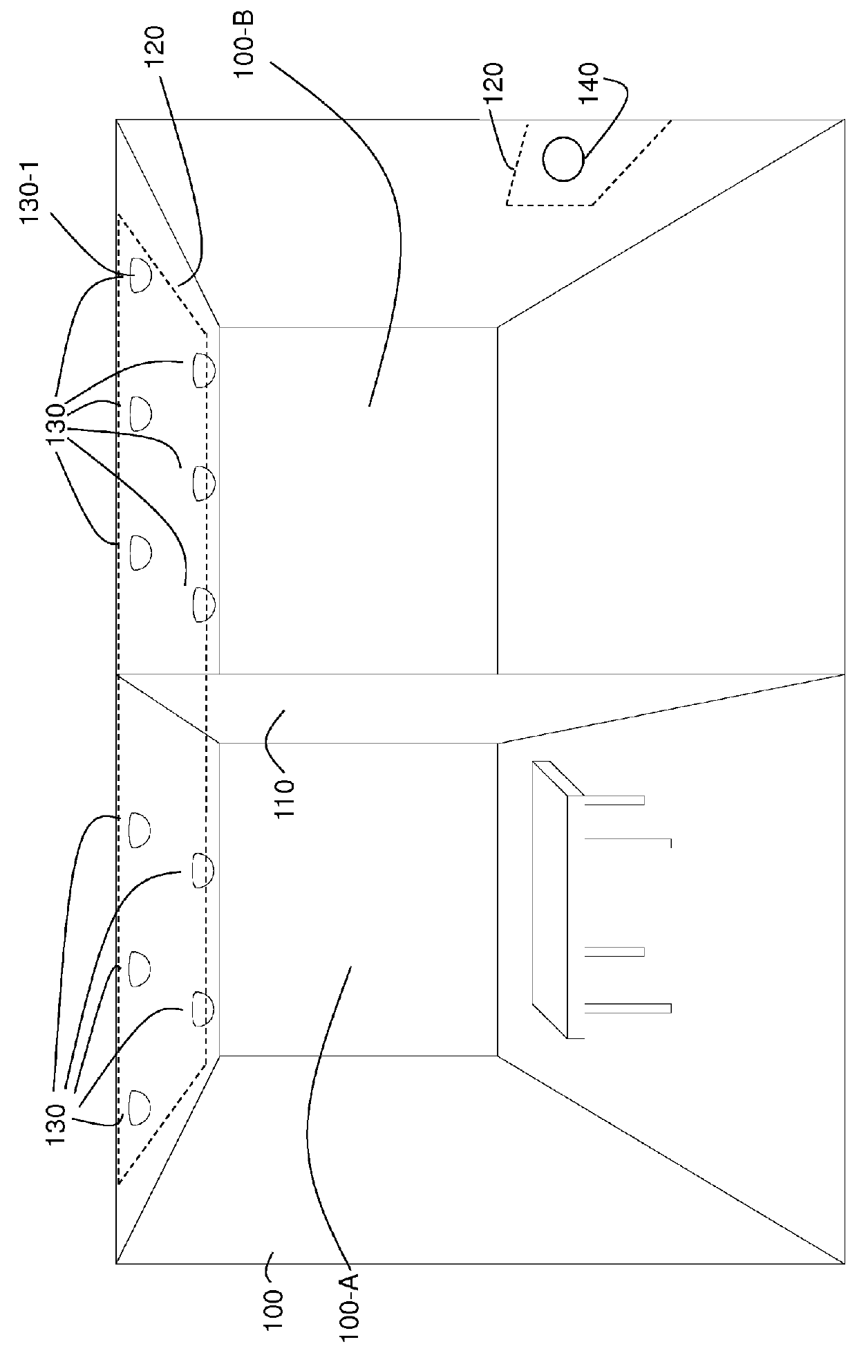
[0033]FIG. 1 illustrates an exemplary structure 100, according to one embodiment of the present invention. As shown in FIG. 1, the structure 100 may, optionally, be separated by a wall 110 into parts of the structure in the form of rooms 100-A and 100-B. In the structure 100 a system 120 is installed. The system 120 comprises a plurality of controllable devices 130. While the devices 130 could comprise any type of devices which may need to be commissioned, such as e.g. components of a heating system or components of a fire alarm system, in the illustrative embodiment shown in FIG. 1, th...


PUM


Abstract

The invention relates to a method enabling commissioning of a system comprising a plurality of controllable devices capable of transmitting their identification signals. The method includes receiving identification signals from the devices, displaying a map of a structure and icons corresponding to the devices from which the identification signals have been received, detecting a first user input indicating a selection by a user of a first icon from the displayed icons, the first icon corresponding to a first device, and, in response to the first user input, providing a command to the first device to issue a cue identifying the first device to the user. The method further includes, subsequent to the first device issuing the cue, detecting a second user input indicating a selection by the user of a location on the map for the first icon, and displaying the first icon on the map at the selected location.

Description

CROSS-REFERENCE TO PRIOR APPLICATIONS[0001]This application is the U.S. National Phase application under 35 U.S.C. § 371 of International Application No. PCT / EP2015 / 050075, filed on Jan. 6, 2015, which claims the benefit of European Patent Application No. 14150709.5, filed on Jan. 10, 2014. These applications are hereby incorporated by reference herein.FIELD OF THE INVENTION[0002]Embodiments of the present invention relate generally to the field of illumination systems, and, more specifically, to systems and methods for commissioning such illumination systems.DESCRIPTION OF THE RELATED ART[0003]Commissioning is a key activity in the deployment of current lighting systems. In short, commissioning refers to the process of configuring a lighting system that takes place after the components of the system, such as e.g. light sources, sensors and wall switches, are installed in a structure and connected to power and, if necessary, to a data network. Each of the installed components typica...

Claims


Application Information

Patent Timeline
Patent Type & Authority Patents(United States)
IPC IPC(8): H05B37/02H04L12/24G06F3/0488G06F3/0484G06F3/0481G08C17/02G06F17/30G06F3/0482
CPCH05B37/0272G06F3/0482G06F3/04817G06F3/04886G08C17/02H04L41/22G06F3/04847G08C2201/30H05B47/165H05B47/19H05B47/195H05B47/10
Inventor TIBERI, LUCAHULTERMANS, MARTIJN MARIUSVONCKEN, RALF GERTRUDA HUBERTUS
Owner SIGNIFY HLDG BV
Why Eureka
Try Eureka