Method for searching a spur in a signal received and device for searching a spur in a signal received

a technology of a spur and a signal received, which is applied in the direction of electrical equipment, transmission monitoring, and very fast steps, can solve the problems of high resolution bandwidth and different errors in the detection of spurs, and achieve the effect of efficient and fast manner

Active Publication Date: 2019-09-10
ROHDE & SCHWARZ GMBH & CO KG
View PDF18 Cites 0 Cited by
  • Summary
  • Abstract
  • Description
  • Claims
  • Application Information

AI Technical Summary

Benefits of technology

[0011]The invention is based on the finding that a two step approach for searching a spur in a signal received reduces the total time for searching the spur provided that the narrow resolution bandwidth used in the detailed sweep measurement is determined automatically such that no manual interaction is required being time-consuming. In the fast sweep measurement, the location of the at least one spur is determined roughly whereas the at least one spur are analyzed in detail in the detailed sweep measurement, in particular its amplitude, frequency and bandwidth. According to the two step approach, two passes, namely two different sweep measurements, are performed which have different measurement configurations and test limits. In the first step, the whole frequency range of the signal received is measured using oversweeping and a high resolution bandwidth. This first step is very fast due to the high resolution bandwidth used. In addition, the locations of the at least one spur can be identified roughly, in particular its frequency in the frequency range. However, the high resolution bandwidth produces different errors regarding the detection of the spur which cannot be corrected appropriately by using mathematical means. Therefore, the second step (detailed sweep measurement) is required in order to accurately identify the at least one spur in the signal received in detail, in particular its properties like amplitude, frequency and bandwidth. The second pass using the narrow resolution bandwidth ensures that different spurs being close to each other can be distinguished, in particular spurs having a frequency at a non integer multiple of the carrier frequency with respect to the harmonics. As already mentioned, the spurs identified in the first step (first pass) are measured separately in the second step (second pass) again wherein the detailed sweep measurement (second step) is automatically configured for accurate measurements. Since the settings for the detailed sweep measurement (second step), in particular the value of the narrow resolution bandwidth, are provided automatically, no manual input of a user is required. Thus, the user does not need to configure certain detailed sweep measurements as the detailed sweep measurements are configured automatically which increases the efficiency while reducing the total time needed for the measurement.
[0025]Further, said device may be configured to perform a method as mentioned above. Thus, the device is configured to search for at least one spur in an efficient and fast manner.

Problems solved by technology

This first step is very fast due to the high resolution bandwidth used.
However, the high resolution bandwidth produces different errors regarding the detection of the spur which cannot be corrected appropriately by using mathematical means.

Method used


Image

  • Method for searching a spur in a signal received and device for searching a spur in a signal received
  • Method for searching a spur in a signal received and device for searching a spur in a signal received

Examples


Embodiment Construction

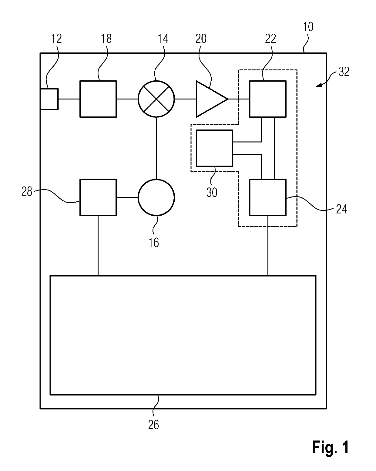
[0029]In FIG. 1, a device 10 is shown having a radio frequency input 12 for receiving a signal to be analyzed wherein the device 10 is configured to search for spurs in the signal received via the input 12.

[0030]The device 10 comprises a mixer 14 which is connected to the input 12 as well as to a tunable local oscillator 16 being a voltage controlled oscillator, for instance.

[0031]Further, an input attenuator 18 is shown which is positioned between the input 12 and the mixer 14 such that the radio frequency signal received via the input 12 is attenuated before it is processed, in particular converted by the mixer 14. The input attenuator 18 can also be called radio frequency attenuator.

[0032]The output of the mixer 14 is connected with a preamplifier 20 that is used to amplify the converted signal before it is received by a resolution bandwidth filter 22 (RBW filter). The resolution bandwidth filter 22 is also called bandpass filter or intermediate frequency filter (IF filter).

[0033...


PUM


Abstract

A method for searching a spur in a signal received is described, wherein a fast sweep measurement with a high resolution bandwidth is performed in order to detect at least one spur. Further, a detailed sweep measurement with narrow resolution bandwidth is performed in order to analyze said spur detected. Said narrow resolution bandwidth needed for said detailed sweep measurement of said spur is determined automatically. Further, a device for searching a spur in a signal received is described.

Description

TECHNICAL FIELD[0001]The invention relates to a method for searching a spur in a signal received and a device for searching a spur in a signal received.BACKGROUND OF THE INVENTION[0002]Spurs, also called spurious emissions and / or spurious signals, are signals at arbitrary frequencies wherein these frequencies do not belong to the carrier signal (desired signal) having a certain frequency. Accordingly, harmonics of that carrier signal having frequencies at an integer multiple of the frequency of the carrier signal can be considered as specific spurs. Further, oscillations and / or mixing terms also correspond to spurs wherein these spurs have frequencies at a non integer multiple of the frequency of the carrier signal. Generally speaking, spurs are signals having unwanted frequencies.[0003]Further, the amplitudes of the spurs are small compared to the amplitude of the fundamental, namely the carrier signal. Thus, the amplitudes of the spurs are usually near the noise floor level of the...

Claims


Application Information

Patent Timeline
Patent Type & Authority Patents(United States)
IPC IPC(8): H04B10/079H04B17/318
CPCH04B17/318
Inventor WOEHRLE, ANKESTEHR, MATTCARONE, BERRYGHEEN, KAY
Owner ROHDE & SCHWARZ GMBH & CO KG
Why Eureka
Try Eureka