Headlight socket with antenna

a headlight socket and antenna technology, applied in the direction of resonant antennas, substantially flat resonant elements, transportation and packaging, etc., can solve the problems of ineffective reception of signals, inability to easily mount printed antennas on the windows of vehicles, and disadvantages of conventional vehicle antenna structures, etc., to enhance the quality of signal reception, facilitate integration, and simplify the effect of the automobile assembly process

Active Publication Date: 2018-06-05
YI CHANG HSIANG INDAL
View PDF4 Cites 0 Cited by
  • Summary
  • Abstract
  • Description
  • Claims
  • Application Information

AI Technical Summary

Benefits of technology

[0005]It is an objective of the present invention to provide a headlight socket which is modularized and efficient in receiving signals while a vehicle mounted with the headlight socket is moving.
[0013]Therefore, according to the embodiments of the present invention, the headlight socket is for use with a vehicle. With the first antenna devices and second antenna device being disposed at the front of the vehicle, signals can best be received from the front of the vehicle while the vehicle is moving, thereby enhancing the quality of signal reception. The headlight socket is advantageously characterized in that conventional vehicular antennas are integrated into a vehicle to manifest the advantages of modularization so that, during an automobile assembly process, an antenna assembly procedure and a headlight assembly procedure are integrated, and in consequence the automobile assembly process is simplified, allowing internal circuits to be readily integrated.

Problems solved by technology

However, the aforesaid conventional vehicle antenna structures have disadvantages.
For example, the printed antennas cannot be easily mounted on the windows of the vehicles, nor are they efficient in receiving signals, because the thermal insulating sheets on the windows using contain metals.
Both the extensible antennas and the fixed antennas are mounted on the surfaces of the car bodies and thus may get damaged readily to the detriment of the beauty of the car bodies.

Method used


Image

  • Headlight socket with antenna
  • Headlight socket with antenna
  • Headlight socket with antenna

Examples


Embodiment Construction

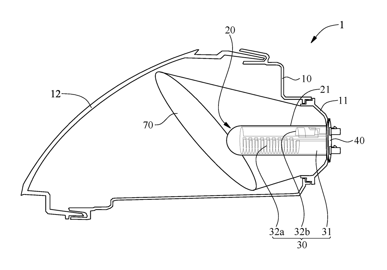
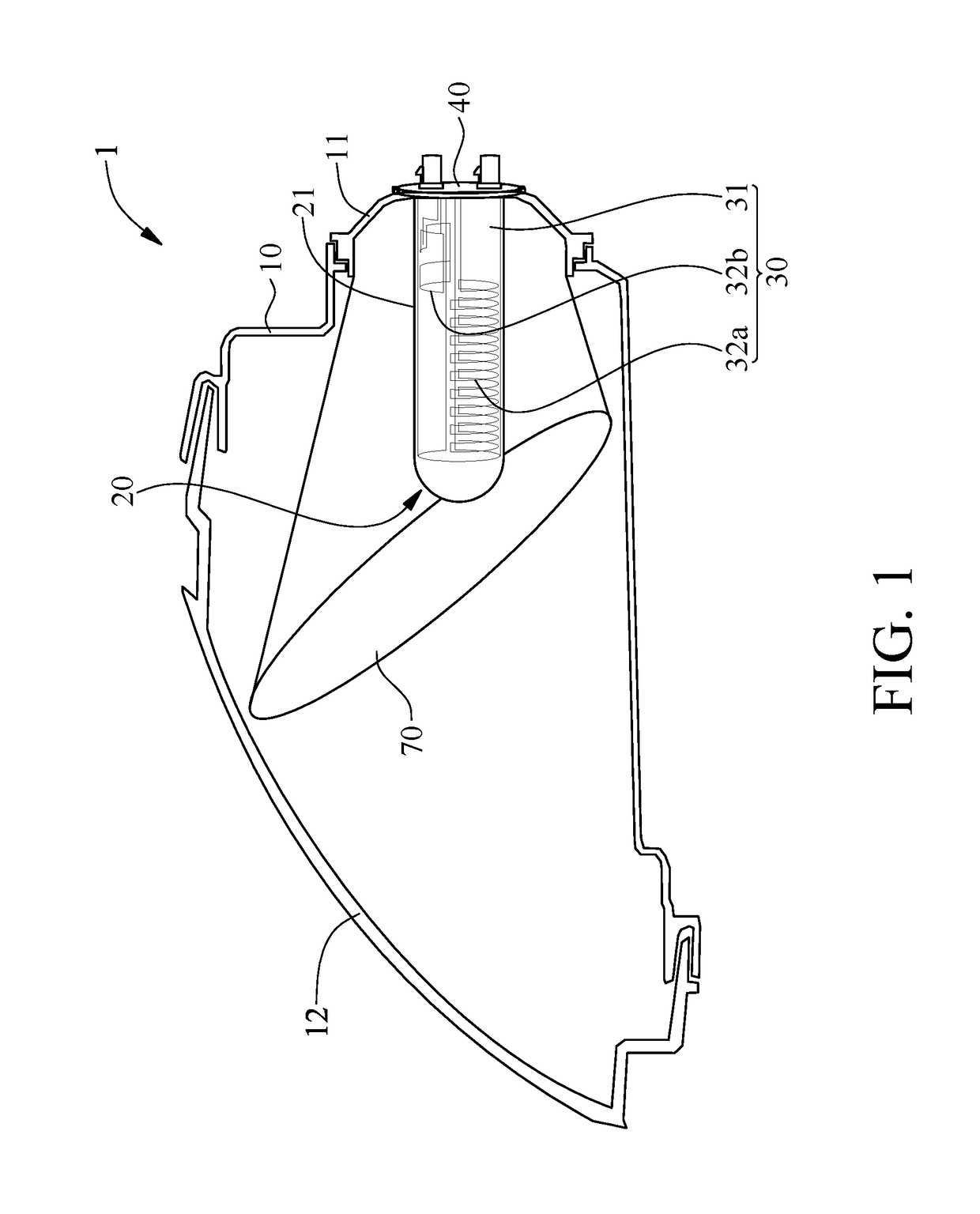
[0021]Referring to FIG. 1 through FIG. 3, a headlight socket 1 according to an embodiment of the present invention comprises a base 10, a cover 20, a first antenna device 30, and a connection stand 40.

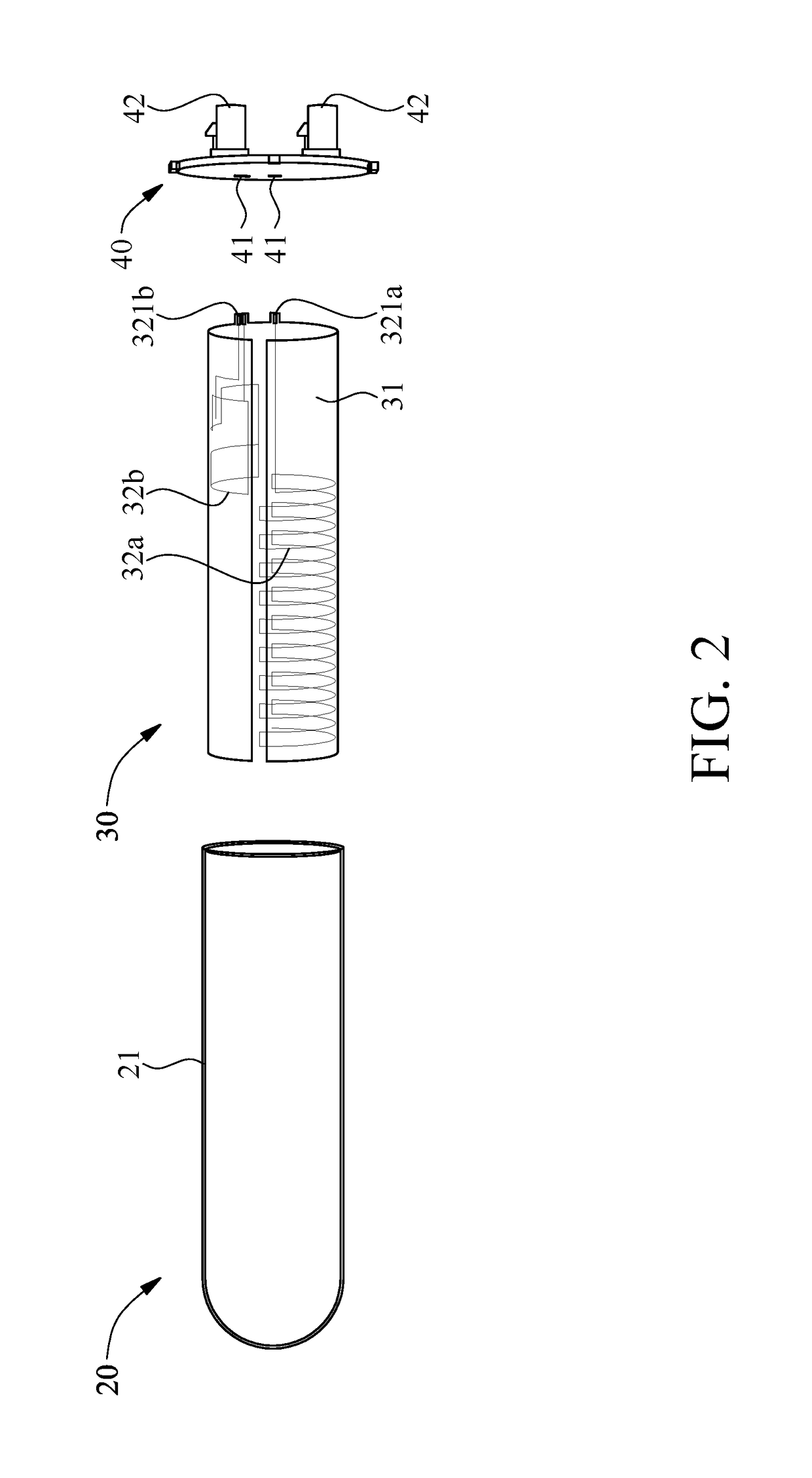
[0022]The base 10 comprises a mounting portion 11. The cover 20 is mounted on the base 10 through the mounting portion 11. The cover 20 has a sidewall 21 that annularly defines a receiving space. The first antenna device 30 is received in the cover 20. The first antenna device 30 comprises a conductive end 321a. The connection stand 40 is coupled to the sidewall 21. The connection stand 40 comprises a connection port 41 in contact and connection with the conductive end 321a.

[0023]Referring to FIG. 2 and FIG. 3, in this embodiment, the cover 20 has a cylindrical receiving space and is closed at one end. The cover 20 is made of any appropriate material, such as glass or plastic, and is either transparent or opaque.

[0024]The first antenna device 30 is a flexible antenna module or a thin-...


PUM


Abstract

A headlight socket with an antenna includes a base, cover, first antenna device and connection stand. The base includes a mounting portion. The cover is mounted on the base through the mounting portion and has a sidewall for annularly defining a receiving space. The first antenna device is received in the cover and includes a conductive end. The connection stand is coupled to the sidewall. The connection stand includes a connection port in contact and connection with the conductive end. The headlight socket is mounted on a vehicle. The first antenna device for receiving signals is disposed at the front of the vehicle, thereby enhancing the quality of signal reception. Conventional vehicular antennas are integrated into the headlight socket to manifest advantages of modularization so that an automobile assembly process is simplified, allowing internal circuits to be readily integrated.

Description

FIELD OF THE INVENTION[0001]The present invention relates to headlight sockets and, more particularly, to a headlight socket with an antenna and modularization advantages.BACKGROUND OF THE INVENTION[0002]Due to technological advancements, additional electronic devices, such as digital televisions (DTV), global positioning systems (GPS), radios, and the like, are increasingly mounted inside a car body, so are the integrated functions thereof. The electronic devices receive and transmit signals by an antenna structure.[0003]Conventional vehicular antenna structures come in the following categories, printed antennas mounted on windows of vehicles, extensible antennas mounted at the rear ends of vehicles, and fixed antennas (such as shark-fin antennas and rod-shaped antennas) mounted on the tops of vehicles.[0004]However, the aforesaid conventional vehicle antenna structures have disadvantages. For example, the printed antennas cannot be easily mounted on the windows of the vehicles, no...

Claims


Application Information

Patent Timeline
Patent Type & Authority Patents(United States)
IPC IPC(8): H01Q1/32B60Q1/00H01Q21/28H01Q9/04H01Q9/42
CPCB60Q1/0017H01Q1/3291H01Q21/28H01Q9/42H01Q9/0407B60Q1/0023
Inventor HSUEH, CHIH-YUAN
Owner YI CHANG HSIANG INDAL
Why Eureka
Try Eureka