Anti-erosion structure for aircrafts

a technology of anti-erosion structure and aircraft, which is applied in the direction of superimposed coating process, efficient propulsion technology, machines/engines, etc., can solve the problems of affecting the use of the blades of helicopters, and affecting the use of the blades

Active Publication Date: 2018-05-29
EURON AERONAUTIC DEFENCE & SPACE +1
View PDF8 Cites 0 Cited by
  • Summary
  • Abstract
  • Description
  • Claims
  • Application Information

AI Technical Summary

Benefits of technology

[0011]Thus, the structure for aircraft according to this invention constitutes an improvement that is very significant in relation to the existing solutions for erosion due to rain and that also has the advantage of protecting against erosion due to sand.
[0013]This multilayer structure makes it possible to optimize the absorption of shocks because the ductile layers act as dampers. This multilayer structure makes it possible to obtain an even better resistance both to erosion due to sand and to erosion linked to rain.

Problems solved by technology

However, it is nonetheless subject to erosion that leads to its replacement before the end of service life.
A problem that arises today is the following: the leading edges of helicopter blades suffer mainly from erosion due to rain, and it is necessary to replace these leading edges before the end of service life of the blade.
In addition, no common solution to erosion due to rain and to erosion due to sand exists, particularly for helicopter blades.
The challenge is multifaceted since erosion represents a cost in maintenance and in repairs, as well as an operational cost due to the aerodynamic losses that the erosion causes.
Finally, the placement of temporary protection against sand erosion represents a significant cost for the user.
These temporary solutions consist in the application of adhesive tapes or even of polymer films that have the advantage of resisting sand erosion well, but the drawback of not resisting rain.

Method used


Image

  • Anti-erosion structure for aircrafts
  • Anti-erosion structure for aircrafts
  • Anti-erosion structure for aircrafts

Examples


Embodiment Construction

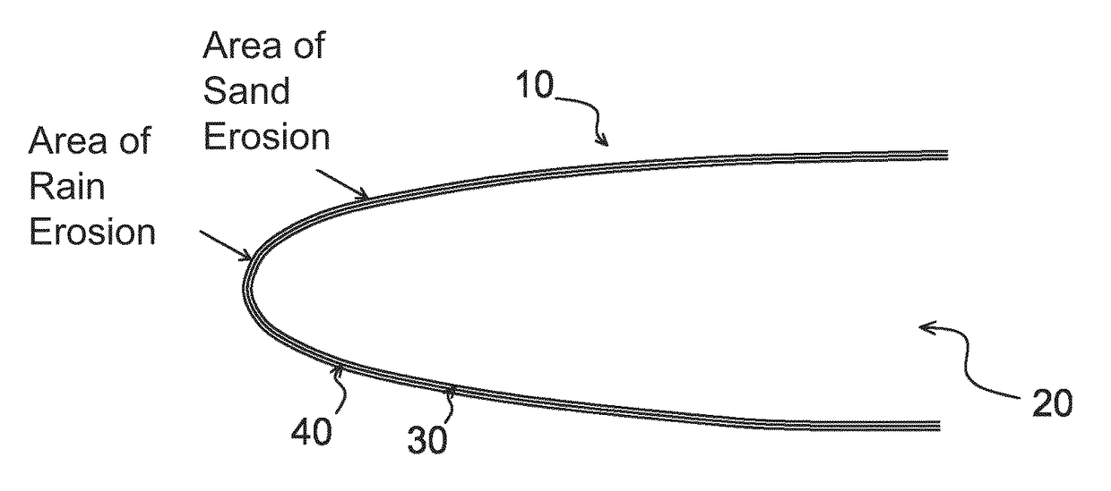
[0030]FIG. 1 illustrates a structure 10 for aircraft that is consistent with this invention in one embodiment. Said structure 10 comprises a part 20 having a leading edge 30 of metal, said leading edge 30 being covered with a coating 40 that has a thickness that is less than or equal to ten micrometers and that exhibits a hardness that is greater than six hundred in Vickers Hardness (HV).

[0031]The areas where erosion due to sand occurs and the areas where erosion due to rain occurs are seen in this FIG. 1.

[0032]This invention constitutes an improvement that is very significant relative to the existing solutions for erosion due to rain and that also has the advantage of protecting against erosion due to sand. It is a matter of improving the strength of the current metallic protection (the leading edge 30 of metal) by a coating 40 that is very hard and with a thickness that is less than ten micrometers. According to this invention, the entire area of the leading edge 30, which is subj...


PUM

PropertyMeasurementUnit
thicknessaaaaaaaaaa
thicknessaaaaaaaaaa
thicknessaaaaaaaaaa

Abstract

A structure (10) for aircrafts, includes a part (20) including a metal leading edge (30), the leading edge (30) being covered by a coating (40) having a thickness which is less than or equal to ten micrometers and having a hardness higher than six hundred in the Vickers hardness test (HV). According to a mode of embodiment, the coating (40) is a multilayer stainless steel coating consisting of a superposition of layers with a low nitrogen gradient and layers with a high nitrogen gradient, the layers having a thickness essentially equal to a micrometer. An aircraft including such a structure is also described.

Description

FIELD OF THE INVENTION[0001]This invention relates to the field of anti-erosion coatings for aircraft leading edges.[0002]This invention aims to bring a solution to the erosion, due to rain and due to sand, of aircraft leading edges (vanes, wings, blades . . . ).[0003]The leading edge can consist of a metal (steel or the like) that is harder than the structure that supports it. However, it is nonetheless subject to erosion that leads to its replacement before the end of service life.STATE OF THE ART[0004]A problem that arises today is the following: the leading edges of helicopter blades suffer mainly from erosion due to rain, and it is necessary to replace these leading edges before the end of service life of the blade. In addition, no common solution to erosion due to rain and to erosion due to sand exists, particularly for helicopter blades.[0005]The challenge is multifaceted since erosion represents a cost in maintenance and in repairs, as well as an operational cost due to the ...

Claims


Application Information

Patent Timeline
Patent Type & Authority Patents(United States)
IPC IPC(8): B64C27/473C23C14/16C23C14/06C23C14/35C23C28/00C23C28/02C23C14/34C23C14/32B64C3/28B64C3/24F01D5/28
CPCB64C3/24B64C27/473C23C14/0605C23C14/0611C23C14/0617C23C14/0641C23C14/0652C23C14/16C23C14/165C23C14/325C23C14/3485C23C14/35C23C28/021C23C28/42F01D5/288B64C3/28B64C2027/4733F05D2240/303Y02T50/673Y02T50/60
Inventor LUISET, BENJAMINNAVARRE, THOMASBOSCHET, PATRICKBILLARD, ALAIN
Owner EURON AERONAUTIC DEFENCE & SPACE
Why Eureka
Try Eureka