Facility communications infrastructure

a communication infrastructure and infrastructure technology, applied in the field of communication systems, can solve the problems of affecting adoption and use, affecting the reliability of the current system, and unable to easily achieve the current system, so as to achieve the effect of reducing the number of changes and costs, and reducing the number of errors

Active Publication Date: 2018-05-22
THE DETECTION GRP
View PDF12 Cites 1 Cited by
  • Summary
  • Abstract
  • Description
  • Claims
  • Application Information

AI Technical Summary

Benefits of technology

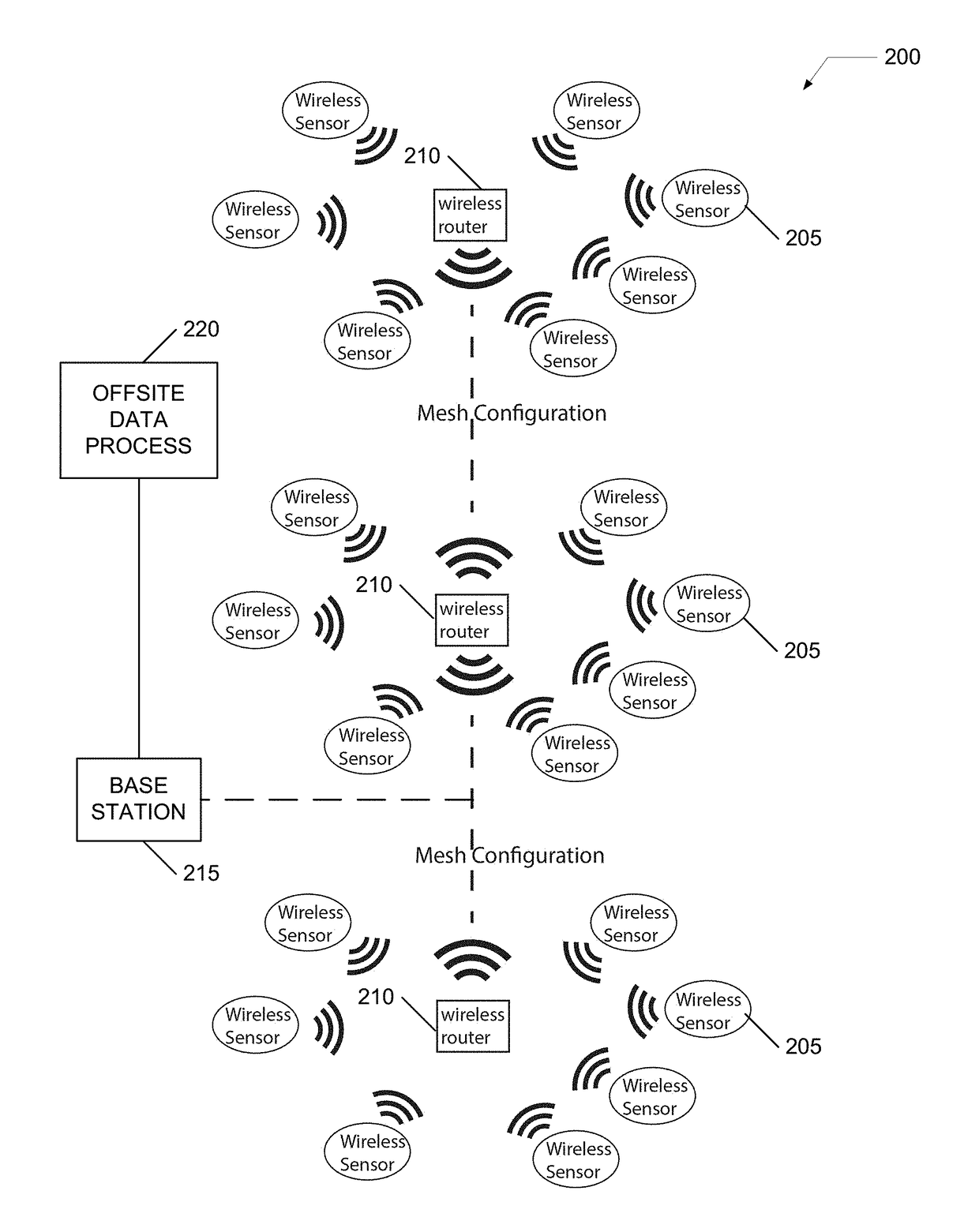
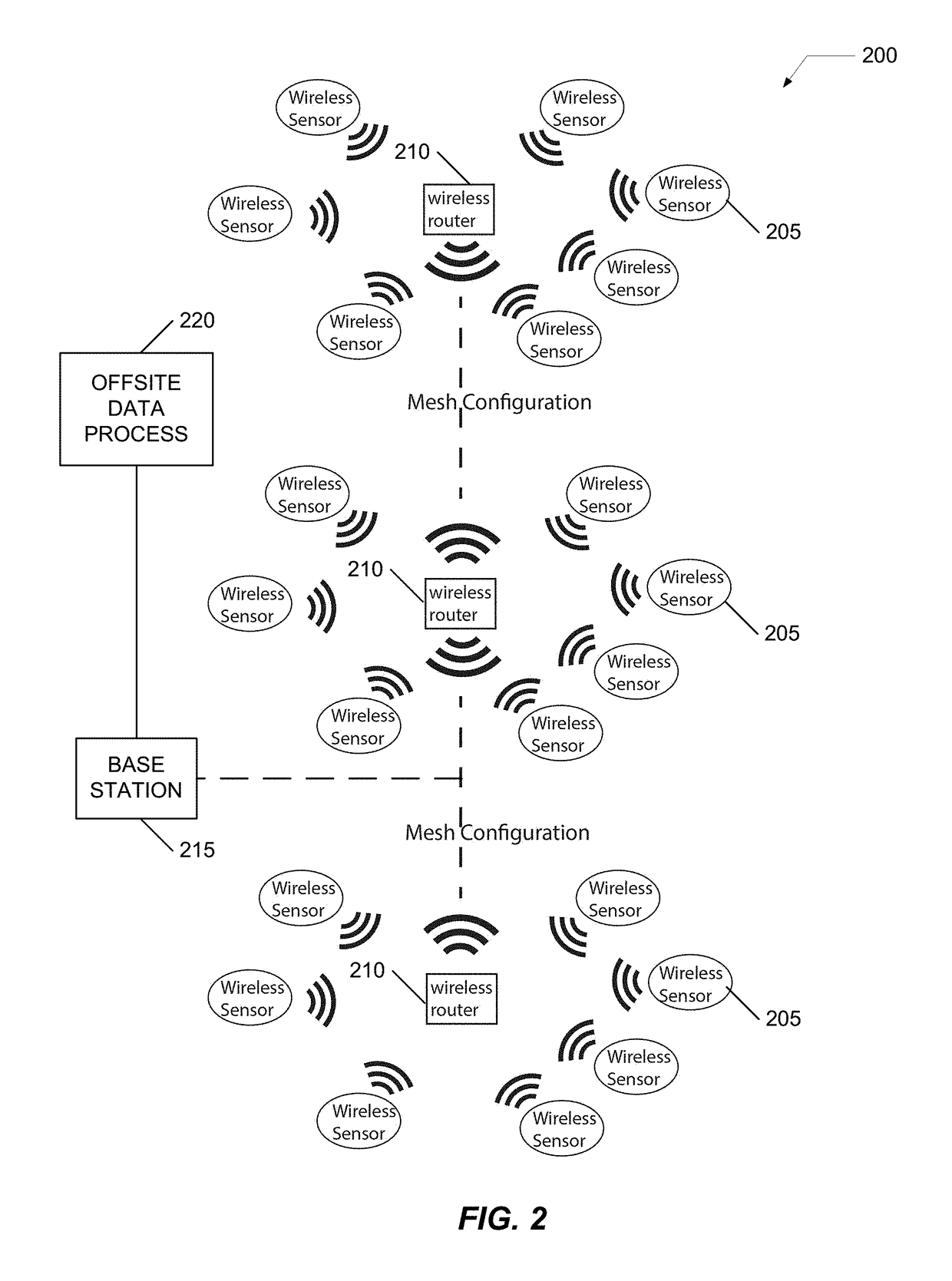
[0010]An embodiment of the present invention includes a system and method for a communications architecture appropriate for distribution of large numbers of wireless sensors throughout a large commercial building and may include as well a simple and efficient mechanism to communicate the sensor information off-site.
[0021]The new system preferably addresses the shortcomings of existing systems, including those described herein, while maintaining high information integrity level and redundant system approach, as well as expanding features as follows: (1) work with the legacy systems already installed and be able to expand them into the new features with minimal changes and costs; (2) installable and operate with minimal training (important for self-install implementations); (3) support the new features, including valve shutoff by individual location, by zone or by both predefined plumbing structures and based on predictive software; extending to linear sensors and other water sensors as needs arise; adding virtually any sensor type, like fire, moisture, and the like; control systems for valve and other controllable devices, including switchgear, lights, thermostats, sprinkler systems, etc.; talk to Building Management Systems (BMS), potentially bi-directionally; predictive analytics, like ultrasonically sensing pipe flow characteristics over time and creating an automated control response to certain aberrations consistent with a leak that might not yet be physically detected; base stations capable of communicating with and controlling virtually any sensor and / or control; the system needs to allow for communications with other IoT based devices protocols when such protocols become standard, which may take several years before that standard is resolved; agnostic for any radio, for example a wireless radiofrequency communications model to be based on longer range 900 MHz transceivers, but also allow for Wi-Fi, Z-Wave, and other standards within the hardware and software architecture.

Problems solved by technology

The current system, although reliable, has some limitations for growth into the Internet of Things (IoT), and with over 16K sensors in the field, there are changes that improve upon the previously disclosed system.
The current system may be limited in some instances, including: (1) limited wireless range (the wireless communications paradigm does not go through floors or within a floor at a distance greater than 300 feet) without the use of relatively expensive repeaters; (2) all sensors are transmit only and cannot receive messages (although not a major issue with most sensors, combined with a POTS line interface, requiring a phone call to be made to transmit to the server, timing of messages therefore can take several attempts to transmit); (3) base stations are required on every floor due to the range and limitations of the current electronics; (4) the number of sensors attached to each base station are limited; (5) base stations are hard wired to the POTS lines, requiring pulling phone lines in the riser, adding to installation costs; (6) the current electronics are expensive compared to current costs and can be substantially reduced using today's architecture and hardware; (7) the aesthetics of the current system would benefit from a dramatic design refresh; (8) although an operator can shut off service to the portal in case of non-payment by a customer, the base station redundancy allows base stations to still call the customer in case of an emergency; (9) the current alkaline batteries used in the systems, although power can last 5-7 years, many tend to leak after 3-4 years, necessitating replacement of not only the batteries, but the sensors itself due to acid damage; (10) installation and provisioning preferably require a fair degree of expertise and training for superior performance; (11) the current system is not capable of easily adding the next level of features cost effectively; (12) the existing system cannot receive signals from other IoT devices.
Large commercial buildings increasingly are offered advantages for large numbers of sensors distributed throughout the building yet the existing architecture offerings have drawbacks that hinder adoption and use.
Many of the buildings were constructed without an easy way to add wired risers to communicate between floors.

Method used


Image

  • Facility communications infrastructure
  • Facility communications infrastructure
  • Facility communications infrastructure

Examples


Embodiment Construction

[0030]Embodiments of the present invention provide a system and method for improving upon limitations of conventional infrastructure communications systems. The following description is presented to enable one of ordinary skill in the art to make and use the invention and is provided in the context of a patent application and its requirements.

[0031]Various modifications to the preferred embodiment and the generic principles and features described herein will be readily apparent to those skilled in the art. Thus, the present invention is not intended to be limited to the embodiment shown but is to be accorded the widest scope consistent with the principles and features described herein.

Definitions

[0032]Unless otherwise defined, all terms (including technical and scientific terms) used herein have the same meaning as commonly understood by one of ordinary skill in the art to which this general inventive concept belongs. It will be further understood that terms, such as those defined i...


PUM


Abstract

A system and method for improving upon limitations of conventional infrastructure communications systems. A sensor architecture may include a multiple protocol communications paradigm to enhance whole building sensor management. A system may have one or more innovations that include anticipatory alarms, nuisance alarm reduction, and big data building profiling.

Description

CROSS REFERENCE TO RELATED APPLICATIONS[0001]This application is a continuation-in-part of U.S. patent application Ser. No. 14 / 985,202 filed 30 Dec. 2015 which in turn claims benefit of U.S. Patent Application No. 62 / 098,991, the contents of these applications are hereby expressly incorporated in their entireties by reference thereto for all purposes.FIELD OF THE INVENTION[0002]The present invention relates generally to communications systems, and more specifically, but not exclusively, to facility communications infrastructure for enabling, supporting, and monitoring communications throughout a large multifloor building and between the building and outside services and facilities.BACKGROUND OF THE INVENTION[0003]The subject matter discussed in the background section should not be assumed to be prior art merely as a result of its mention in the background section. Similarly, a problem mentioned in the background section or associated with the subject matter of the background section...

Claims


Application Information

Patent Timeline
Patent Type & Authority Patents(United States)
IPC IPC(8): G08B29/00H04Q9/00H04W4/00H04W4/70
CPCH04W4/70H04Q9/00H04Q2209/40
Inventor SLEVIN, RICHARD S.ANDERSON, STEVENLOH, TECK EEPAULUS, GLEN MICHAEL
Owner THE DETECTION GRP
Why Eureka
Try Eureka