Travel assistance device

a technology for assistance devices and objects, applied in automatic initiations, brake systems, instruments, etc., can solve problems such as inability to assist in collision avoidance between vehicles and objects, and does not consider at all whether an object is positioned on a roadway or on a sidewalk, so as to reduce the time

Active Publication Date: 2018-05-08
TOYOTA JIDOSHA KK
View PDF6 Cites 2 Cited by
  • Summary
  • Abstract
  • Description
  • Claims
  • Application Information

AI Technical Summary

Benefits of technology

[0012]According to this aspect, annoyance the passenger feels for the application of braking force is reduced, as will be described in detail later, since excessive braking force is not applied when the possibility of collision between the vehicle and a pedestrian is relatively low (that is, when the object is predicted not to be positioned in the second part).
[0028]In the second aspect of the disclosure, the at least one electronic control unit may be configured to reduce a time until when the vehicle terminates deceleration, by adjusting a time at which the braking force is applied to the vehicle.

Problems solved by technology

In this case, the person who was positioned on the sidewalk may collide with a vehicle.
However, the travel assistance device, described in Japanese Patent No. 4637890, does not consider at all whether an object is positioned on a roadway or on a sidewalk.
This means that there is room for improvement in the travel assistance device described in Japanese Patent No. 4637890 in that the device cannot assist in collision avoidance between a vehicle and an object in consideration of whether the object is positioned on a roadway or on a sidewalk.

Method used


Image

  • Travel assistance device
  • Travel assistance device
  • Travel assistance device

Examples


first embodiment

(1) Vehicle 1 in a First Embodiment

[0057]A vehicle 1 in the first embodiment will be described below. The vehicle 1 in the first embodiment is a vehicle to which an embodiment of the “first travel assistance device that sets an assistance range” is applied.

(1-1) Configuration of Vehicle 1 in the First Embodiment

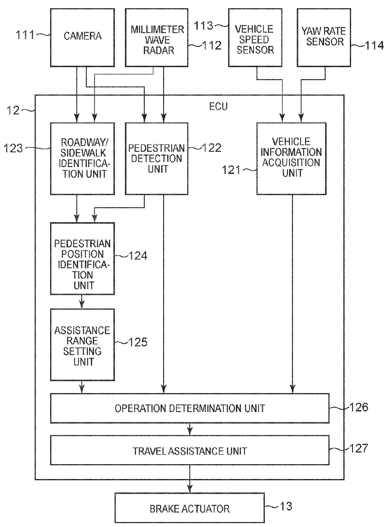
[0058]The configuration of the vehicle 1 in the first embodiment will be described with reference to FIG. 1. As shown in FIG. 1, the vehicle 1 includes a camera 111 that is one specific example of a “detection unit”, a millimeter wave radar 112 that is one specific example of a “detection unit”, a vehicle speed sensor 113, a yaw rate sensor 114, an Electronic Control Unit (ECU) 12 that is one specific example of the “travel assistance device” described above, and a brake actuator 13.

[0059]The camera 111 is a capturing device that captures the area ahead of the vehicle 1. The millimeter wave radar 112 uses millimeter waves to detect objects around the vehicle 1. The vehicle sp...

second embodiment

(2) Vehicle 2 in a Second Embodiment

[0100]Next, a vehicle 2 in a second embodiment will be described. The vehicle 2 in the second embodiment is a vehicle to which an embodiment of the “first travel assistance device that sets a movement range” described above is applied.

(2-1) Configuration of Vehicle 2 in the Second Embodiment

[0101]The configuration of the vehicle 2 in the second embodiment will be described with reference to FIG. 8. It should be noted that the same reference numerals are attached to the same components as those of the vehicle 1 in the first embodiment, and a detailed description thereof will be omitted.

[0102]As shown in FIG. 8, the vehicle 2 in the second embodiment is different from the vehicle 1 in the first embodiment in that an ECU 22 is provided instead of the ECU 12. The ECU 22 is different from the ECU 12 in that a moving speed setting unit 225, which is one specific example of the “setting unit” described above, is provided instead of the assistance range s...

third embodiment

(3) Vehicle 3 in a Third Embodiment

[0111]Next, a vehicle 3 of the third embodiment will be described. The vehicle 3 in the third embodiment is a vehicle to which an embodiment of the “second travel assistance device” described above is applied.

(3-1) Configuration of Vehicle 3 in the Third Embodiment

[0112]The configuration of the vehicle 3 in the third embodiment will be described with reference to FIG. 11. It should be noted that the same reference numerals are attached to the same components as those of the vehicle 1 in the first embodiment, and a detailed description thereof will be omitted.

[0113]As shown in FIG. 11, the vehicle 3 in the third embodiment is different from the vehicle 1 in the first embodiment in that an ECU 32 is provided instead of the ECU 12. The ECU 32 is different from the ECU 12 in that an assistance level setting unit 325 is provided instead of the assistance range setting unit 125. The assistance level setting unit 325 sets an assistance level that defines ...


PUM


Abstract

A travel assistance device includes an actuator and an electronic control unit. The electronic control unit is configured to predict a future position of a vehicle and an object, set an assistance range around the vehicle, determine whether an avoidance start condition is satisfied and in which of a first roadway area, a second roadway area, and a sidewalk area the object is positioned, set the avoidance start condition and a movement range of the object, so that the avoidance start condition is more easily determined to be satisfied when the object is in the first roadway area than when the object is in the second roadway area, and more easily determined to be satisfied when the object is in the second roadway area than when the object is in the sidewalk area, and perform a collision avoidance operation when the avoidance start condition is satisfied.

Description

INCORPORATION BY REFERENCE[0001]The disclosure of Japanese Patent Application No. 2016-141343 filed on Jul. 19, 2016 including the specification, drawings and abstract is incorporated herein by reference in its entirety.BACKGROUND1. Technical Field[0002]The present disclosure relates to a travel assistance device.2. Description of Related Art[0003]A travel assistance device is known that assists in collision avoidance between a vehicle and an object by applying braking force to the vehicle when there is a possibility that the vehicle and the object will collide (for example, see Japanese Patent No. 4637890).SUMMARY[0004]An object that may collide with a vehicle is sometimes positioned not only on a roadway but also on a sidewalk. More specifically, when the object is a person, there is a possibility that a person on a sidewalk will jump out onto a roadway. In this case, the person who was positioned on the sidewalk may collide with a vehicle. In another case, when the object is a tw...

Claims


Application Information

Patent Timeline
Patent Type & Authority Patents(United States)
IPC IPC(8): B60T7/22G08G1/16
CPCB60T7/22G08G1/166B60T2250/04B60T2210/32B60T2250/03B60T2201/022G08G1/167B60T2201/08G06V20/56B60W30/08
Inventor TOCHIGI, KOHEIFUJITA, KAZUYUKINAGATA, SHINICHISATO, MINAMI
Owner TOYOTA JIDOSHA KK
Why Eureka
Try Eureka