Resonant control device and resonant control method thereof

a resonant control device and control method technology, applied in the direction of electric variable regulation, process and machine control, instruments, etc., can solve the problems of high-frequency state with more switching loss and noise, the frequency f of the pwm signal cannot endlessly increase, and the volume and efficiency requirement of conventional power converters cannot be met. , to achieve the effect of improving the light-load efficiency of a resonant converter, reducing the start-up resonant current, and increasing the lower-limit range range o

Active Publication Date: 2018-05-01
MEANWELL GUANGZHOU ELECTRONICS
View PDF7 Cites 5 Cited by
  • Summary
  • Abstract
  • Description
  • Claims
  • Application Information

AI Technical Summary

Benefits of technology

This patent is for a device and method that controls the frequency of signals in a resonant converter. The device sets a switch value based on the minimum and maximum frequencies of the signals, which results in a lower-limit range of output voltage and a wider range of operation. This improves the efficiency of the converter, reduces start-up current, and minimizes noise. The method requires no additional hardware.

Problems solved by technology

Presently, a conventional power converter cannot satisfy requirement for volume and efficiency.
However, owning to hardware limitation, the frequency F of the PWM signal cannot endlessly increase whereby the half-bridge resonant converter cannot operate in a wide range.
Besides, in PWM mode, the high-frequency state has more switching loss and higher noise.
For digital control, since a PWM module of the signal controller 10 has insufficient resolution, the output voltage Vo is easily unstable.

Method used


Image

  • Resonant control device and resonant control method thereof
  • Resonant control device and resonant control method thereof
  • Resonant control device and resonant control method thereof

Examples


Embodiment Construction

[0019]Reference will now be made in detail to embodiments illustrated in the accompanying drawings. Wherever possible, the same reference numbers are used in the drawings and the description to refer to the same or like parts. In the drawings, the shape and thickness may be exaggerated for clarity and convenience. This description will be directed in particular to elements forming part of, or cooperating more directly with, methods and apparatus in accordance with the present disclosure. It is to be understood that elements not specifically shown or described may take various forms well known to those skilled in the art. Many alternatives and modifications will be apparent to those skilled in the art, once informed by the present disclosure.

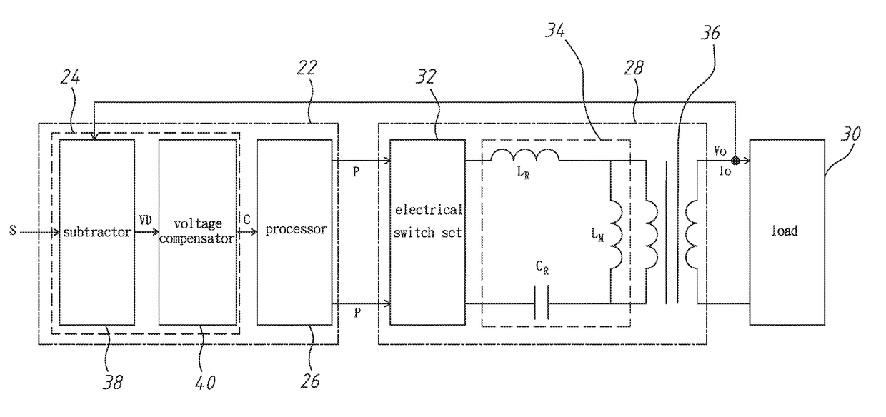
[0020]Refer to FIG. 3 and FIG. 4. The resonant control device 22 of the present invention is introduced as below. The resonant control device 22 comprises a feedback controller 24 and a processor 26. The feedback controller 24 is connected with a...


PUM


Abstract

A resonant control device and a resonant control method thereof controls a resonant converter connected with a load. An output voltage is applied across the load. Firstly, a setting voltage is used to perform voltage compensation on the output voltage to generate a control value. Then, pulse modulation signals are generated according to the control value and a switch value, so as to drive the resonant converter to regulate the output voltage. Each pulse modulation signal has the maximum frequency and the minimum frequency. The switch value is equal to the minimum frequency divided by the maximum frequency and less than 0.5. Finally, the process determines whether the control value is less than the switch value. If the answer is yes, PWM signals as the pulse modulation signals are generated, and their frequency is less than the maximum frequency to increase a lower-limit range of the output voltage.

Description

BACKGROUND OF THE INVENTIONField of the Invention[0001]The present invention relates to a resonant control technology applied to a power supply, particularly to a resonant control device and a resonant control method thereof.Description of the Related Art[0002]In recent years, various electronic products develop toward preciseness and minimization. Presently, a conventional power converter cannot satisfy requirement for volume and efficiency. The power converter is asked to improve its power density. When the power semiconductor technology matured in 1970, a switching power supply was widely applied. Thus, nowadays, a switch mode power supply (SMPS) with high efficiency is important in power industry.[0003]The switching power supply uses a half-bridge resonant converter or a full-bridge resonant converter with high efficiency. Take a half-bridge resonant converter for example, as shown in FIG. 1. The half-bridge resonant converter includes a signal controller 10, a first electrical ...

Claims


Application Information

Patent Timeline
Patent Type & Authority Patents(United States)
IPC IPC(8): H02M3/335H02M3/337H02M1/36H02M1/00
CPCH02M3/33507H02M3/335H02M3/3376H02M3/33546H02M1/36H02M2001/0058H02M3/337H02M3/005H02M3/155Y02B70/10H02M1/0058H02M3/33573H02M3/01H02M3/33571
Inventor LU, SHAO-JIE
Owner MEANWELL GUANGZHOU ELECTRONICS
Why Eureka
Try Eureka