Danger zone monitoring at a grade crossing

a technology for monitoring devices and danger zones, applied in the direction of instruments, transportation and packaging, using reradiation, etc., can solve the problem that the scanning of danger zones using electronic devices may be limited to stored sector elements, and achieve the effect of simplifying the setup of the devi

Active Publication Date: 2018-04-24
ROBERT BOSCH GMBH
View PDF17 Cites 1 Cited by
  • Summary
  • Abstract
  • Description
  • Claims
  • Application Information

AI Technical Summary

Benefits of technology

[0008]It is the object of the present invention to create a device for danger zone monitoring at a grade crossing using a radar sensor with which the set-up of the device is simplified.
[0015]A particularly simple set-up of the device is achieved in that the device is designed to determine the danger zone to be monitored by linking the information on the position of traffic paths with information on the position of barrier straight lines, the position of the traffic paths and the position of the barrier straight lines being detected. Thus the danger zone is able to be detected automatically, without this depending on an exact alignment or positioning of the radar sensor with the danger zone to be monitored. The device makes it possible automatically to detect the danger zone to be monitored reliably and with high accuracy. This substantially simplifies the planning of danger zone monitoring. In addition, because of the automatic identification of the danger zone, a high reliability of the monitoring is made possible. Possible errors during the installation and alignment of the radar sensor are able to be corrected, since the position and the extension of the danger zone to be monitored is calibrated with the aid of real object recordings. It is also advantageous that no further aids are required for setting up the monitoring of a danger zone, since the identification of the danger zone is able to take place with the aid of objects such as barriers, trains, vehicles, etc., that appear anyway in the later operation of the danger zone monitoring.

Problems solved by technology

Alternatively, sector elements of the danger zone may be stored according to length and angle, and the scanning of the danger zone using electronic devices may be limited to the stored sector elements.

Method used


Image

  • Danger zone monitoring at a grade crossing
  • Danger zone monitoring at a grade crossing
  • Danger zone monitoring at a grade crossing

Examples


Embodiment Construction

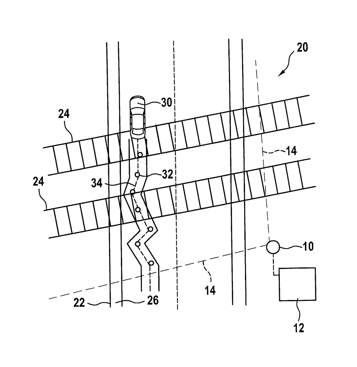
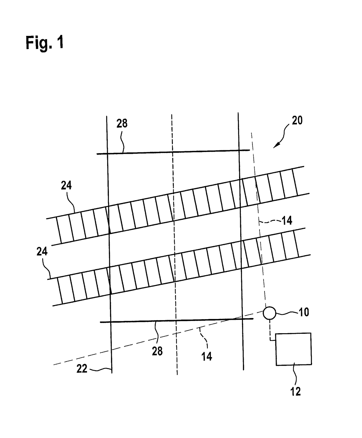
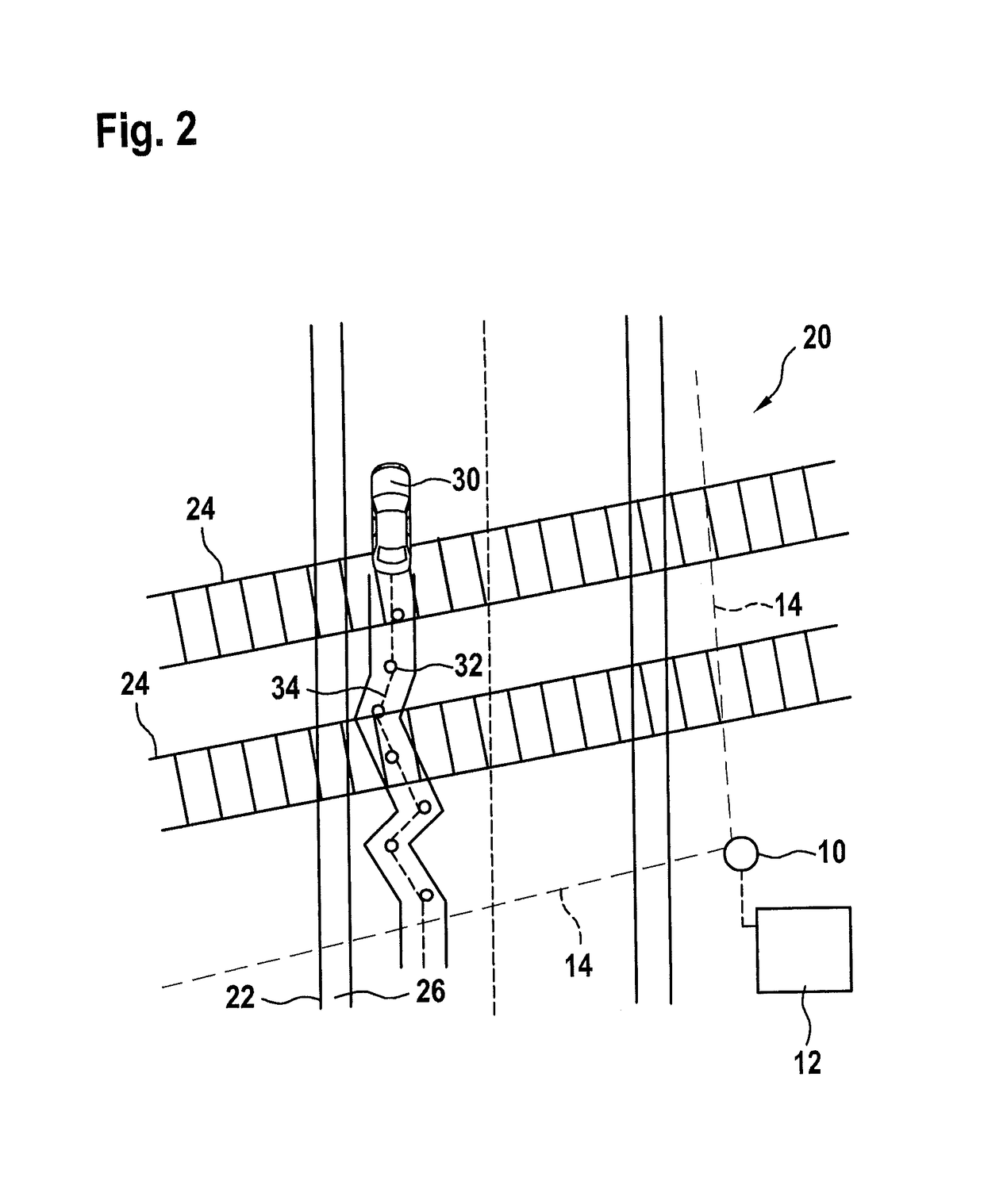
[0037]FIG. 1 schematically shows a radar sensor 10 and an identification unit 12 that is connected to it or integrated into it. Radar sensor 10 is an FMCW radar sensor having a send / receive device, which includes a patch antenna array, and has a schematically shown field of view 14 which includes an azimuth angle range of at least 90°. A plurality of antenna elements are situated horizontally offset with respect to one another. Field of view 14 preferably includes an azimuth angle range of at least 160°.

[0038]Radar sensor 10 is situated at the edge of a danger zone 20 of a grade crossing, which is included in field of view 14.

[0039]In field of view 14 there is a road 22 that crosses danger zone 20 as well as a railroad track, crossing road 22, having tracks 24. Furthermore, for instance, in field of view 14 a pedestrian path 26 (FIG. 2) runs, that crosses the railroad track, through danger zone 20, which is part of road 22.

[0040]FIG. 1 also schematically shows barriers 28 of the gra...


PUM


Abstract

In a method for identifying a danger zone to be monitored at a grade crossing, the following are performed: at least one radar sensor is situated at the danger zone; object trajectories from sequences over time of object positions of respective objects moving through the danger zone are ascertained by the radar sensor; the position of at least one traffic path is identified with the aid of an accumulation of object trajectories; the positions of barrier straight lines are ascertained with the aid of radar reflections of the closed barriers; and the danger zone is determined by linking information on the identified position of the at least one traffic path with information on the ascertained position of the barrier straight lines.

Description

BACKGROUND OF THE INVENTION[0001]1. Field of the Invention[0002]The present invention relates to a device for monitoring a danger zone at a grade crossing, which has a system having at least one radar sensor situated at the danger zone, in particular, having at least one radar sensor for monitoring the danger zone, in whose field of view the danger zone lies.[0003]2. Description of the Related Art[0004]Published German patent document DE 10 2007 032 091 B3 describes a method for monitoring a grade crossing, in which an image is first taken, using cameras directed in a first direction and cameras directed in the opposite direction, of an object located on a road section on one side of a danger zone, and by comparing this image with the image of another camera, the object in a road section lying on the other side of the danger zone is recognized. This is supposed to enable making a notification that the danger zone at a grade crossing is clear of objects.[0005]Published German patent ...

Claims


Application Information

Patent Timeline
Patent Type & Authority Patents(United States)
IPC IPC(8): G01S13/04B61L29/30B61L23/04B61L29/00G01S7/41G01S13/72G01S13/88
CPCB61L29/30B61L23/041G01S13/88G01S7/411G01S13/72B61L29/00
Inventor LEHNERTZ, BENEDIKT
Owner ROBERT BOSCH GMBH
Why Eureka
Try Eureka