Danger zone monitoring at a grade crossing

Active Publication Date: 2015-11-12
ROBERT BOSCH GMBH
View PDF12 Cites 3 Cited by
  • Summary
  • Abstract
  • Description
  • Claims
  • Application Information

AI Technical Summary

Benefits of technology

The present invention is a device for monitoring danger zones at grade crossings using a radar sensor. The device is designed to automatically detect the danger zone by linking information on the positions of traffic paths and barrier straight lines. This simplifies the set-up of the device and allows for reliable and accurate monitoring without the need for precise alignment or positioning of the radar sensor. The device can correct errors during installation and alignment and does not require additional aids for set-up. The identification of the danger zone is made possible by using objects that appear naturally in the monitoring process, such as barriers, trains, and vehicles. Overall, the invention provides a simple and effective solution for monitoring danger zones at grade crossings.

Problems solved by technology

Alternatively, sector elements of the danger zone may be stored according to length and angle, and the scanning of the danger zone using electronic devices may be limited to the stored sector elements.

Method used


Image

  • Danger zone monitoring at a grade crossing
  • Danger zone monitoring at a grade crossing
  • Danger zone monitoring at a grade crossing

Examples


Embodiment Construction

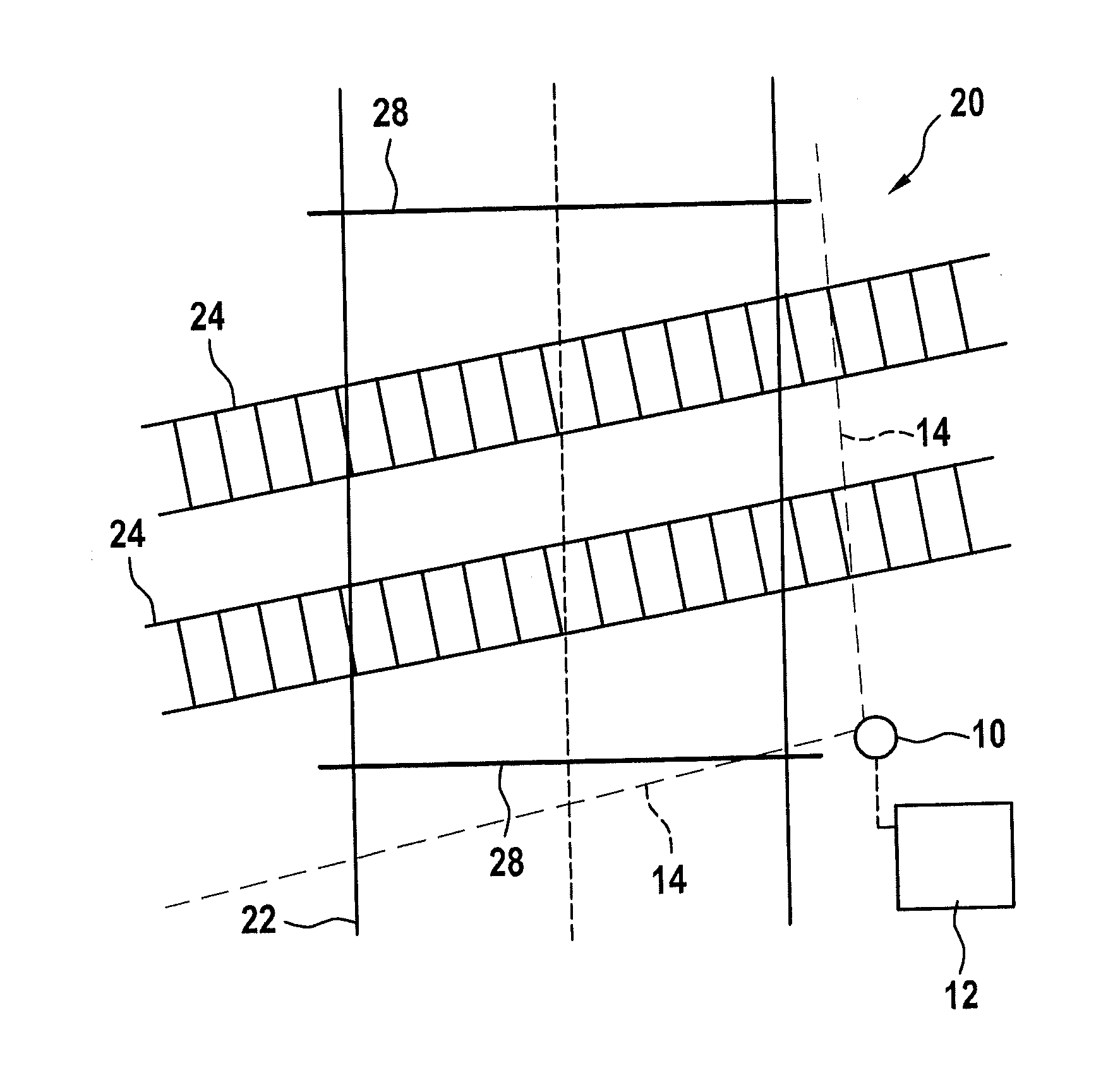
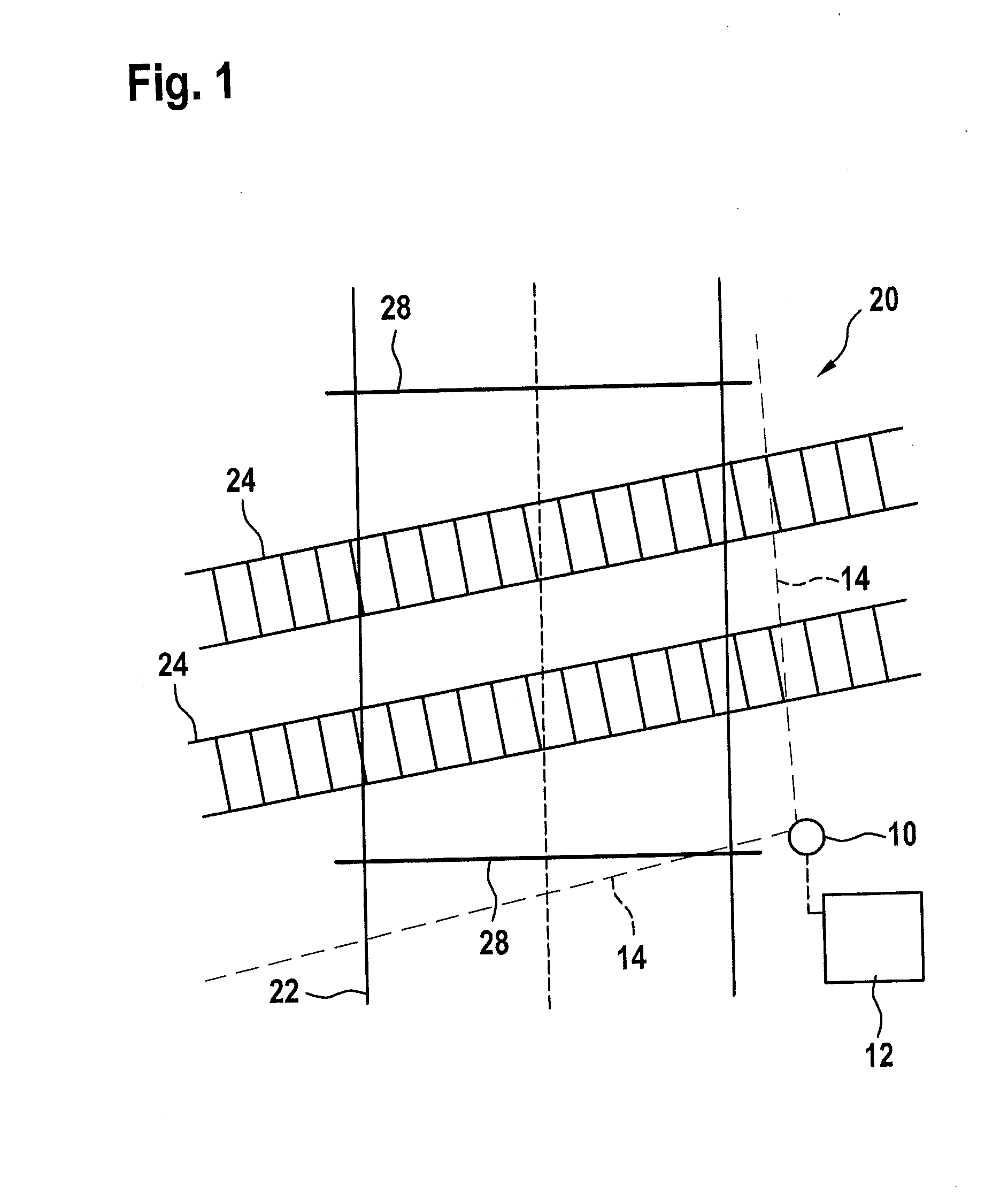
[0037]FIG. 1 schematically shows a radar sensor 10 and an identification unit 12 that is connected to it or integrated into it. Radar sensor 10 is an FMCW radar sensor having a send / receive device, which includes a patch antenna array, and has a schematically shown field of view 14 which includes an azimuth angle range of at least 90°. A plurality of antenna elements are situated horizontally offset with respect to one another. Field of view 14 preferably includes an azimuth angle range of at least 160°.

[0038]Radar sensor 10 is situated at the edge of a danger zone 20 of a grade crossing, which is included in field of view 14.

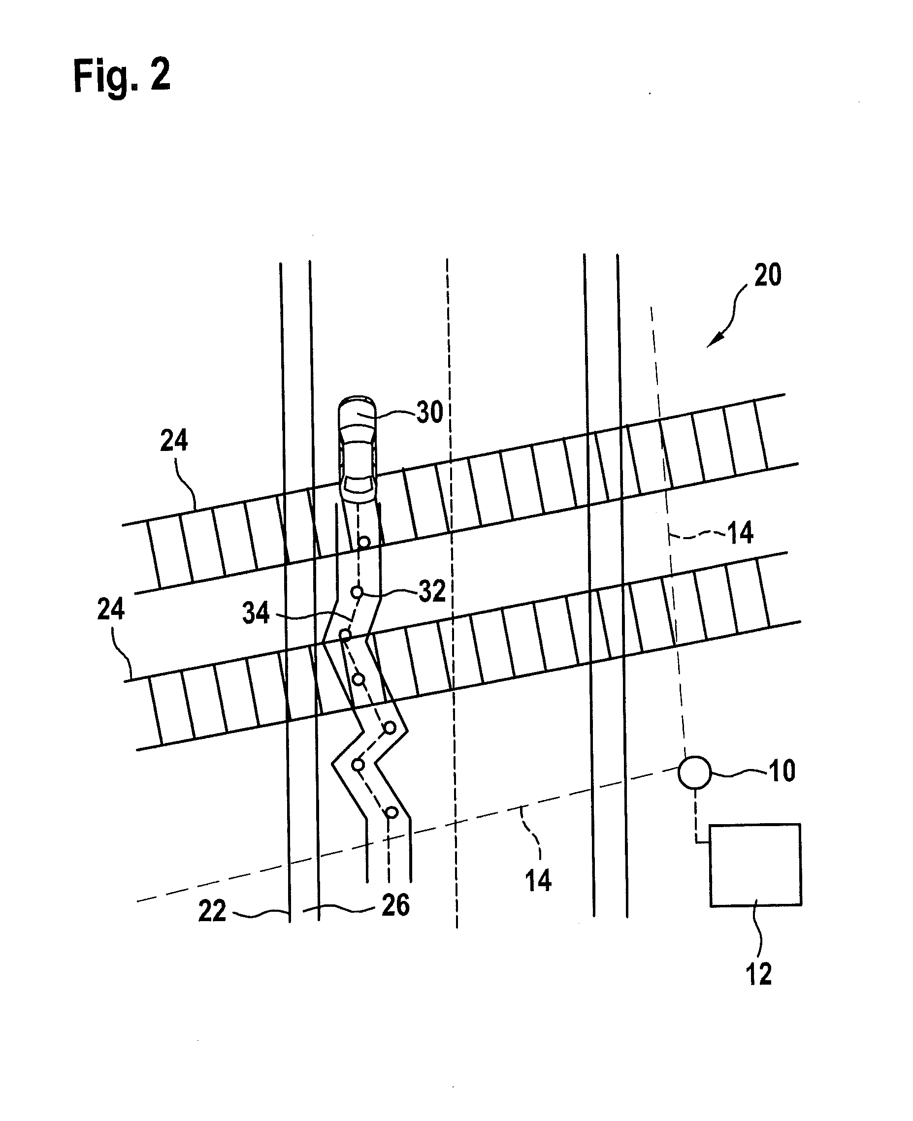
[0039]In field of view 14 there is a road 22 that crosses danger zone 20 as well as a railroad track, crossing road 22, having tracks 24. Furthermore, for instance, in field of view 14 a pedestrian path 26 (FIG. 2) runs, that crosses the railroad track, through danger zone 20, which is part of road 22.

[0040]FIG. 1 also schematically shows barriers 28 of the gra...


PUM


Abstract

In a method for identifying a danger zone to be monitored at a grade crossing, the following are performed: at least one radar sensor is situated at the danger zone; object trajectories from sequences over time of object positions of respective objects moving through the danger zone are ascertained by the radar sensor; the position of at least one traffic path is identified with the aid of an accumulation of object trajectories; the positions of barrier straight lines are ascertained with the aid of radar reflections of the closed barriers; and the danger zone is determined by linking information on the identified position of the at least one traffic path with information on the ascertained position of the barrier straight lines.

Description

BACKGROUND OF THE INVENTION[0001]1. Field of the Invention[0002]The present invention relates to a device for monitoring a danger zone at a grade crossing, which has a system having at least one radar sensor situated at the danger zone, in particular, having at least one radar sensor for monitoring the danger zone, in whose field of view the danger zone lies.[0003]2. Description of the Related Art[0004]Published German patent document DE 10 2007 032 091 B3 describes a method for monitoring a grade crossing, in which an image is first taken, using cameras directed in a first direction and cameras directed in the opposite direction, of an object located on a road section on one side of a danger zone, and by comparing this image with the image of another camera, the object in a road section lying on the other side of the danger zone is recognized. This is supposed to enable making a notification that the danger zone at a grade crossing is clear of objects.[0005]Published German patent ...

Claims


Application Information

Patent Timeline
IPC IPC(8): G01S13/88G01S7/41B61L29/00G01S13/72
CPCG01S13/88B61L29/00G01S7/411G01S13/72B61L29/30B61L23/041
Inventor LEHNERTZ, BENEDIKT
Owner ROBERT BOSCH GMBH
Why Eureka
Try Eureka