
Polarization filtering for window self-emission due to aero-thermal heating

a filtering and window technology, applied in the field of optical systems, can solve the problems of reducing the snr of the target and the ability of the guidance unit to track the target, causing a gradient in the detected signal, and window self-emissions can raise the general background noise, so as to improve the snr of the detected target radiation and reduce the snr of the sensed target emission

Active Publication Date: 2018-03-27
RAYTHEON CO
View PDF8 Cites 0 Cited by
  • Summary
  • Abstract
  • Description
  • Claims
  • Application Information

AI Technical Summary

Benefits of technology

The present invention provides an optical system for use with flight vehicles that allows for better tracking of targets despite extreme heating. The system uses a special optical window that self-emits light, which can interfere with target tracking. To solve this problem, a polarizer is used to filter out the self-emitted light, resulting in a higher signal-to-noise ratio for the detected target radiation. The polarizer uses a filter pixel to impart a linear polarization to the incident light. This improves the quality of the detected target radiation and removes the effects of non-uniform heating. The system can be used with imaging or non-imaging detectors.

Problems solved by technology

However, in guided missiles or sensor pods there can be many different sources of parasitic radiation or “noise” that reduces the SNR of the target and the ability of the guidance unit to track the target.
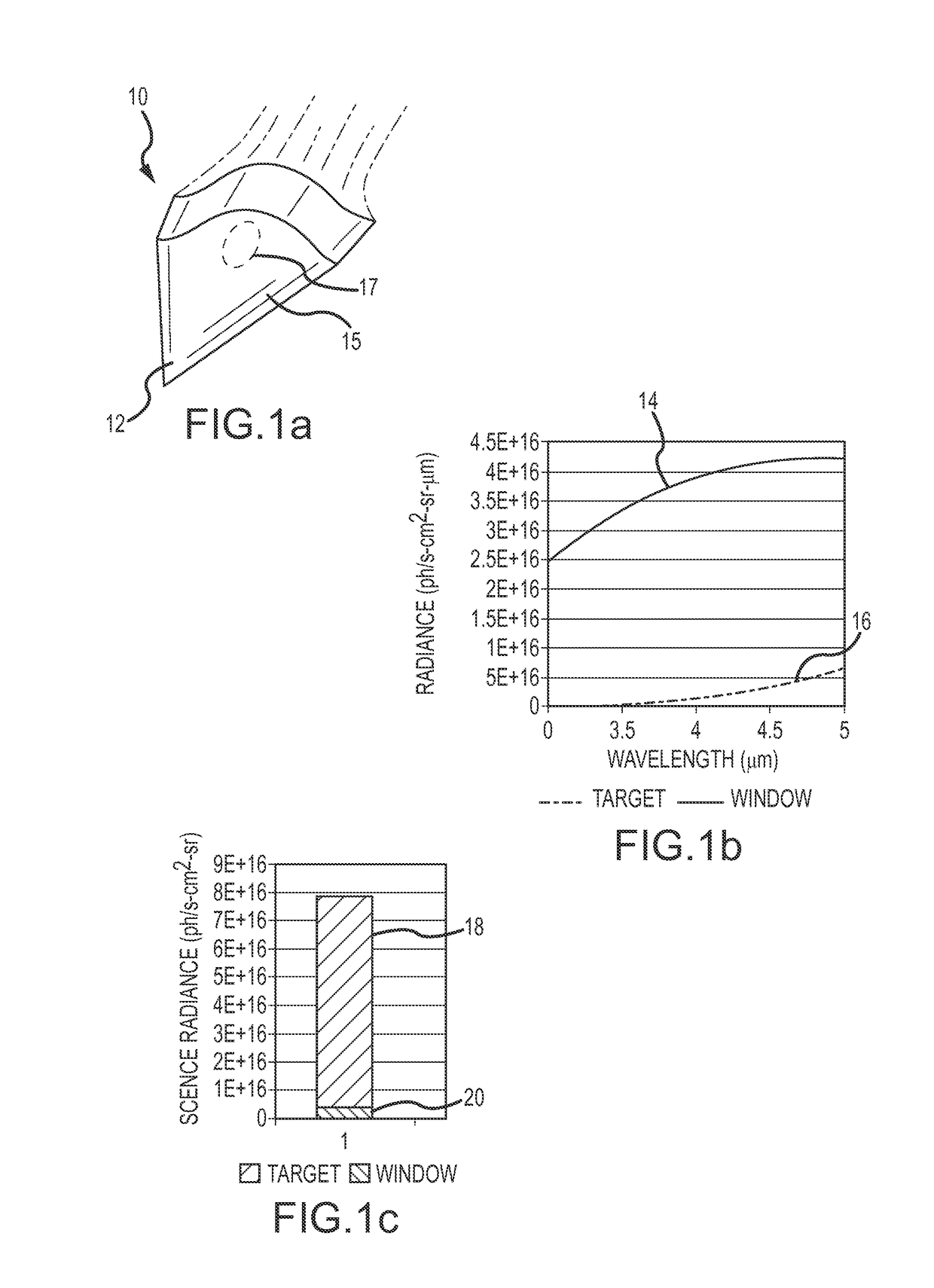
The window self-emissions can raise the general background noise or can induce a gradient in the detected signal (due to non-uniform heating of the window).
In many instances, the self-emissions due to aero-thermal heating are insignificant.
Non-uniform aero-thermal heating can induce a gradient in the window self-emissions, hence the total detected incident radiation.
The disadvantage is that the method of blurring must be carefully designed so that the target is not inadvertently subtracted from the final image.

Method used


Image

  • Polarization filtering for window self-emission due to aero-thermal heating
  • Polarization filtering for window self-emission due to aero-thermal heating
  • Polarization filtering for window self-emission due to aero-thermal heating

Examples


first embodiment

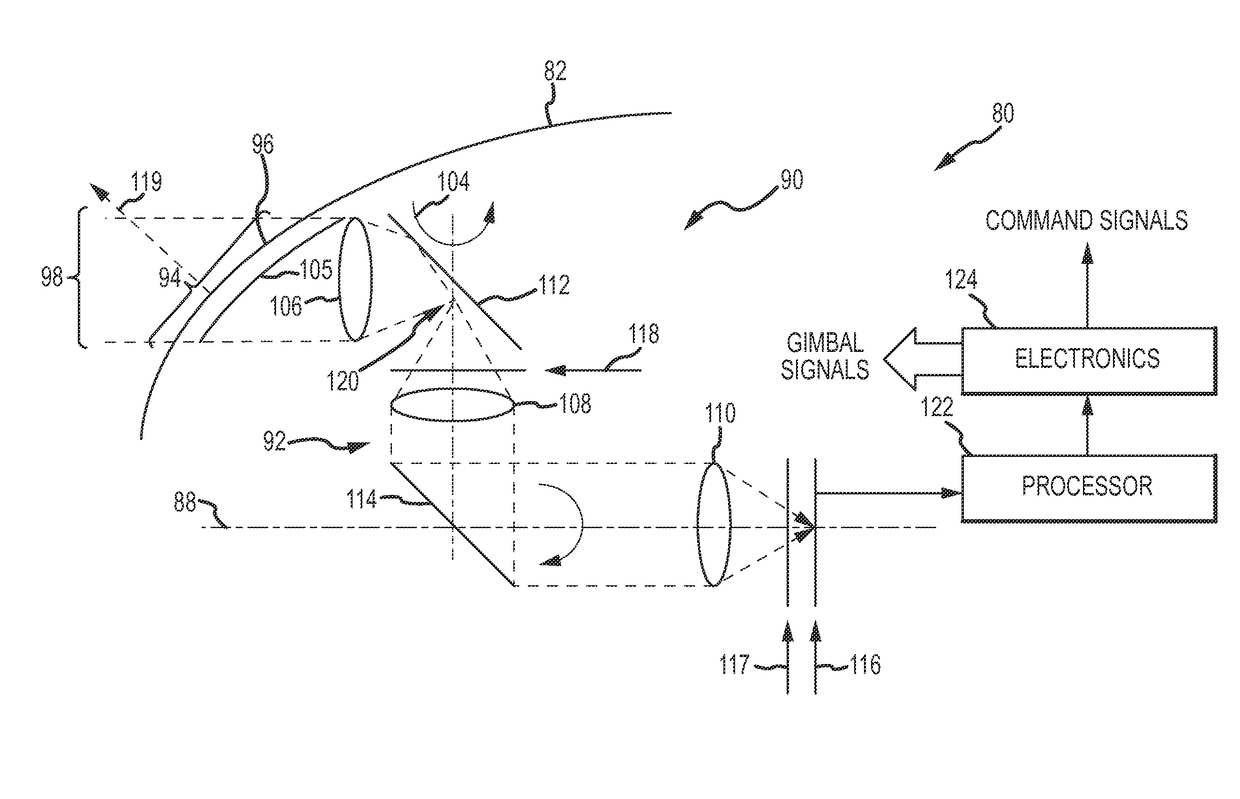
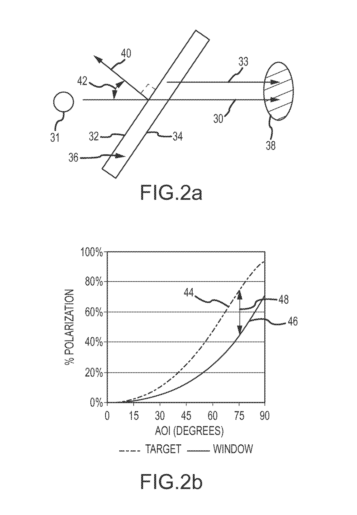
[0051]A polarizer is positioned in optical path between the off-axis segment 96 of optical window and a detector 116 (e.g., quad-cell or FPA) positioned at or near the focal plane. In a first embodiment, a polarizer 117 may be positioned off-gimbal. If polarizer 117 is a sheet polarizer it can be positioned at any arbitrary position along the optical path. If polarizer 117 is a microgrid polarizer it must be positioned at the FPA or an intermediate image of the focal plane. If off-gimbal, the polarizer is only aligned to the plane of incidence (as defined by surface normal 119 to the optical window) at a specified roll / nod orientation (e.g., 0°, 0°) and an orientation 180° out of phase (e.g., 180°, 180°). To read out the detector, the gimbal is rotated to one of these two positions. The “mechanism” for aligning the polarizer is thus implemented by the nod gimbal and rotation of the nod gimbal. As will be discussed further, if the sheet polarizer is implemented with a dynamic microgr...

second embodiment

[0052]In a second embodiment, a polarizer 118 is positioned on the nod gimbal 102 (“on-gimbal”). If polarizer 118 is a sheet polarizer it can be positioned anywhere in the optical path on the nod gimbal and optically aligned to the plane of incidence, and remains in the plane of incidence as the roll and nod gimbals rotate about their respective axes. As shown in FIG. 4b, the lines of the sheet polarizer indicate the direction of the pass axis. If polarizer 118 is a microgrid polarizer it must be positioned at an intermediate image 120 of the focal plane on the nod gimbal and optically aligned to the plane of incidence, and remains in the plane of incidence as the roll and nod gimbals rotate about their respective axis.

[0053]A processor(s) 122 processes the signal to generate data produces. For a sheet polarizer, the processor generates a radiance image. For a microgrid polarizer, the processor may generate a radiance image, an AoLP image and a DoLP image. Electronics 124 use the da...


PUM


Abstract

In flight vehicles subject to extreme aero-thermal heating of the optical window, the optical system is configured to look through an off-axis segment of the optical window and a polarizer is positioned in the optical path between the off-axis segment and the detector. The polarizer comprises at least one filter pixel that imparts a linear polarization of a certain angular value to filter the incident radiation as a function of its polarization. In the case of a sheet polarizer, the entire polarizer is aligned to the plane of incidence. The sheet polarizer preferentially filters the target radiation to increase the SNR at the detector. In the case of a microgrid polarizer, at least one and preferably multiple filter pixels in each sub-array aligned to the plane of incidence. The microgrid polarizer can produce data products including a radiance image, an AoLP image and a DoLP image, only the AoLP image removes the self-emitted window radiance and an gradient caused by non-uniform aero-thermal heating.

Description

BACKGROUND OF THE INVENTION[0001]Field of the Invention[0002]This invention relates to optical systems for use with flight vehicles subject to extreme aero-thermal heating in which window self-emission reduces the signal-to-noise ratio (SNR) of sensed target emissions complicating the task of target tracking.[0003]Description of the Related Art[0004]Optical systems for use with flight vehicles such as guided missiles or belly-mounted sensor pods on aircraft typically include an optical window (e.g., a dome) that protects the sensitive optical and electrical components. The optical window is transparent in a desired spectral band (e.g., the MWIR band from 3-5 microns) to pass emissions from a target in a scene through the optical window to the entrance pupil of focusing optics, which in turn route the incident radiation along an optical path and focus the radiation onto a detector. The detector may, for example, be a quad-cell detector for non-imaging applications such as spot tracki...

Claims


Application Information

Patent Timeline
Patent Type & Authority Patents(United States)
IPC IPC(8): F41G7/22G01S3/781G01J1/04B64C1/14F42B10/46
CPCG01J1/0429B64C1/1484G01S3/781F41G7/2293F42B10/46F41G7/2253F42B15/08F42B15/34
Inventor FEST, ERIC C.
Owner RAYTHEON CO
Learn More