Expandable drop device

a technology of drop device and ball seat, which is applied in the field of drop device, can solve the problems of difficult retrieval process and failure of retrieval process, and achieve the effect of faster and more reliable way

Inactive Publication Date: 2018-03-27
WELLTEC AS
View PDF14 Cites 5 Cited by
  • Summary
  • Abstract
  • Description
  • Claims
  • Application Information

AI Technical Summary

Benefits of technology

[0006]It is an object of the present invention to wholly or partly overcome the above disadvantages and drawbacks of the prior art. More specifically, it is an object to provide an improved way of stimulating several production zones in a faster and more reliable way than with prior art solutions.
[0007]The above objects, together with numerous other objects, advantages, and features, which will become evident from the below description, are accomplished by a solution in accordance with the present invention by a downhole system for a well producing hydrocarbon-containing fluid, comprising:
[0013]By sealing off the first zone from the second zone, acid can be pumped down into the formation without passing the drop device further down the well. In this way, the acid is not wasted, as the rest of the well is sealed off by the sealing element.
[0057]pressurising the well filled with fluid, thereby forcing the drop device to move the sleeve from a closed position to an open position,

Problems solved by technology

Using this ball dropping process is inexpensive, but also very time-consuming since the balls have to be retrieved one by one.
Furthermore, retrieving a round ball rolling in a ball seat can be very difficult, and the retrieval process may therefore fail.

Method used


Image

  • Expandable drop device
  • Expandable drop device
  • Expandable drop device

Examples


Embodiment Construction

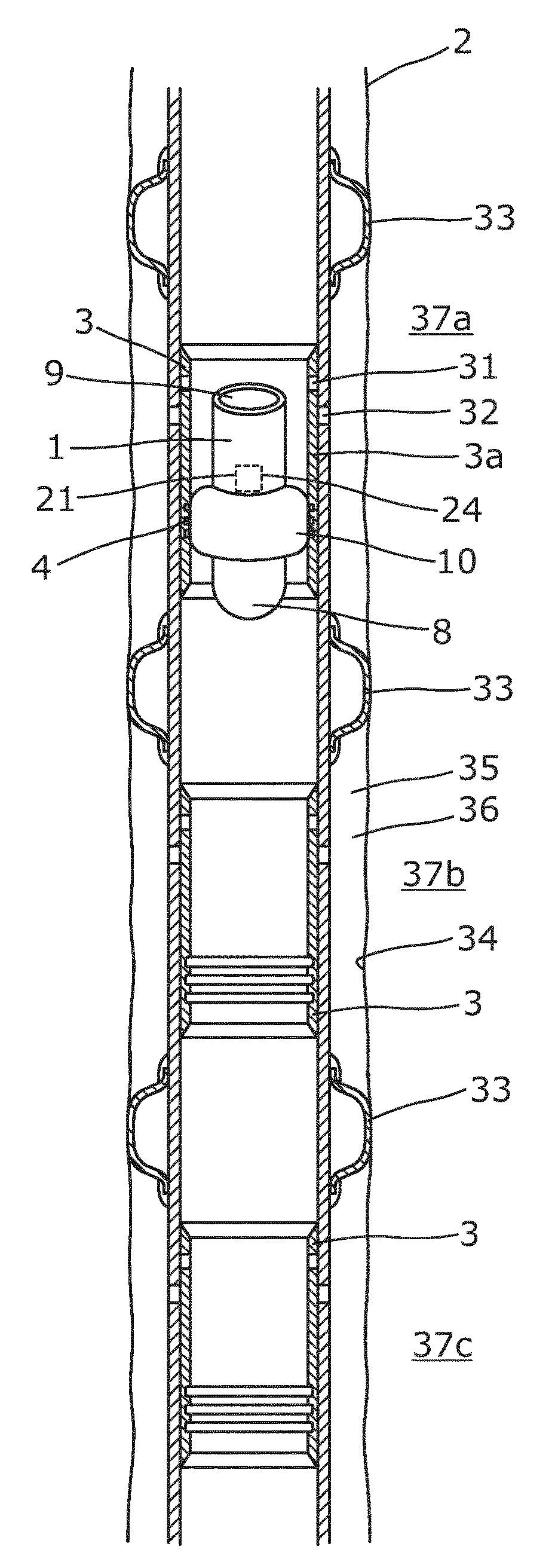
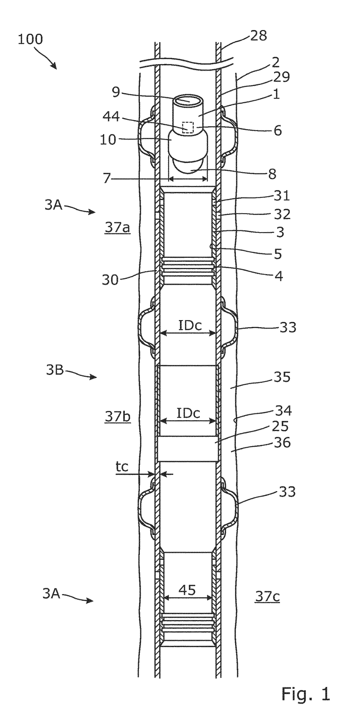
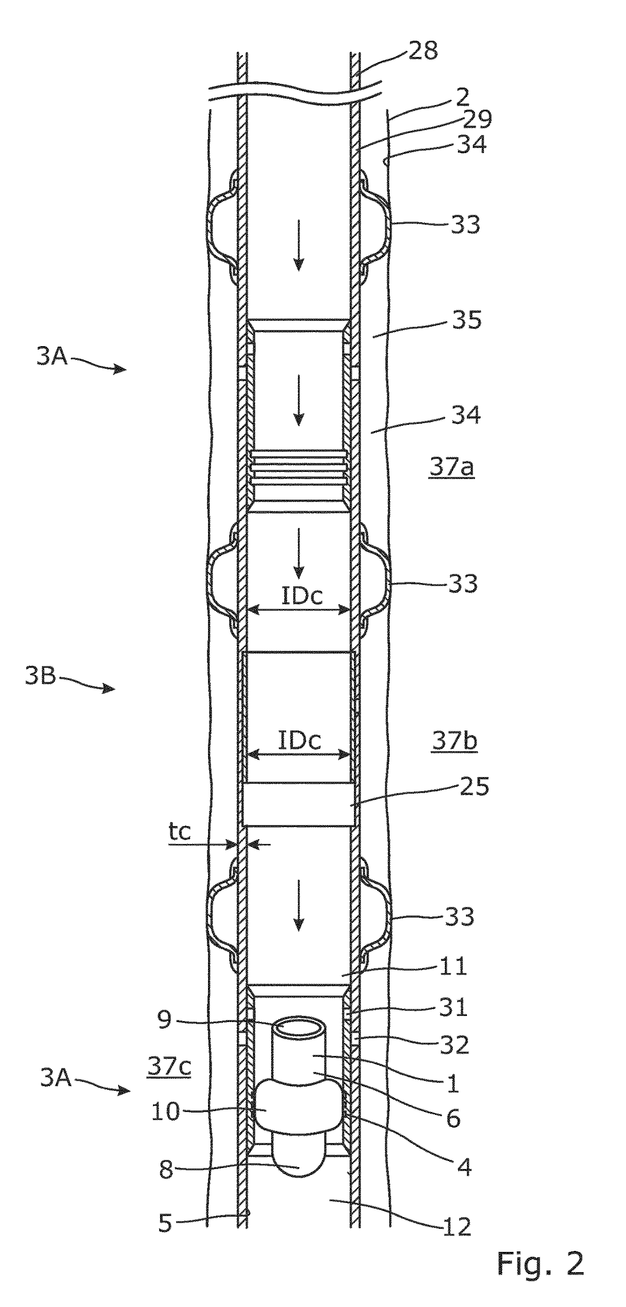
[0081]FIG. 1 shows a downhole system having a casing 30 with several sleeves 3 and a drop device 1 being immersed into the casing 30 of a well 2. The casing 30 has a first casing part 28 and a second casing part 29, and the second casing part comprises the sleeves 3. The second casing part 29 has a casing thickness tc and is substantially a monobore, meaning that the second casing part has an inner diameter IDc which varies by less than twice the casing thickness and thus does not hinder hydrocarbon-containing fluid from flowing freely in the casing 30.

[0082]In prior art, the sleeves are provided with a projecting flange or seat decreasing the inner diameter by 50 percent. This restriction decreases the flow of hydrocarbon-containing fluid substantially because the sleeves may be opened just by dropping a ball or a similar element seating in the restriction.

[0083]The sleeves 3 in FIG. 1 may have a profile 4 on their inner face 5 for a device to engage and open the sleeve so that flu...


PUM


Abstract

The present invention relates to a downhole system for a well producing hydro-carbon-containing fluid. The downhole system comprises a casing comprising a first casing part and a second casing part, the second casing part having a casing thickness and comprising at least one sleeve having an inner face, and the second casing part being substantially a monobore in that the second casing part has an inner diameter which varies by less than twice the casing thickness; and a drop device for being immersed into the casing having at least one sleeve having an inner face. The drop device comprises a body having a width; a leading end; and a trailing end. The body further comprises an expandable sealing element arranged between the leading end and the trailing end, moving from a first position in which fluid is allowed to pass the device and a second position in which the sealing element abuts the inner face of the sleeve and seals off a first zone in the well from a second zone in the well. Furthermore, the invention relates to a downhole system and a stimulation method.

Description

[0001]This application is the U.S. national phase of International Application No. PCT / EP2013 / 069010 filed 13 Sep. 2013, which designated the U.S. and claims priority to EP Patent Application No. 12184463.3, filed 14 Sep. 2012, the entire contents of each of which are hereby incorporated by reference.FIELD OF THE INVENTION[0002]The present invention relates to a drop device for being immersed into a well having a casing with at least one sleeve having a profile and an inner face. Furthermore, the invention relates to a downhole system and a stimulation method.BACKGROUND ART[0003]When stimulating production zones in wells, a first ball is dropped into the well and flows with the well fluid until it reaches a ball seat which it cannot pass, causing the ball to seat in the ball seat of a first sleeve. A continuous pumping of fluid into the well then results in a pressure on the ball moving the sleeve from a closed position to an open position. As the sleeve opens, the fluid enters the ...

Claims


Application Information

Patent Timeline
Patent Type & Authority Patents(United States)
IPC IPC(8): E21B34/14E21B43/25E21B33/127E21B43/14E21B43/26E21B33/124E21B34/12E21B34/00
CPCE21B43/25E21B33/124E21B33/1275E21B34/14E21B43/14E21B43/26E21B34/12E21B2034/007E21B34/142E21B43/27E21B2200/06
Inventor HALLUNDB.AE BUTTED.K, JORGENKRUGER, CHRISTIAN
Owner WELLTEC AS
Why Eureka
Try Eureka