
System and method for virtually tracking a surgical tool on a movable display

a technology of surgical tools and movable displays, applied in the field of system and method for virtually tracking a surgical tool on a movable display, can solve problems such as screen difficulty

Active Publication Date: 2018-03-20
AURIS HEALTH INC
View PDF29 Cites 249 Cited by
  • Summary
  • Abstract
  • Description
  • Claims
  • Application Information

AI Technical Summary

Benefits of technology

[0011]The invention comprises a virtual window system that creates a visual coherency between the image of the patient and his or her anatomy and the patient by aligning the image of the patient anatomy on the display to the patient and presenting the image to the user that feels is if the user is looking directly into the patient through the display. The invention is designed to also display medical devices, such as a minimally invasive tool. The invention makes the anatomy and the motion of the minimally invasive medical device in the display match the motion of the physician's hands by substantially unifying the coordinate systems of the patient, the medical device, the display, and the physician's hands. The invention creates a visual coherency between the motion of the medical device in the image and the motion of the physician's hands manipulating the device. This invention also creates a visual coherency between the motion of the image in the display and display.
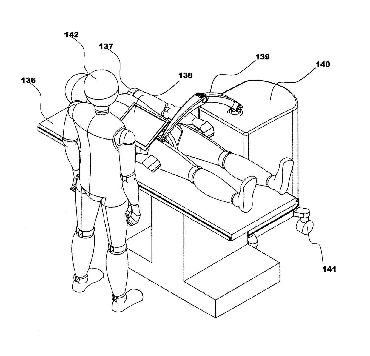
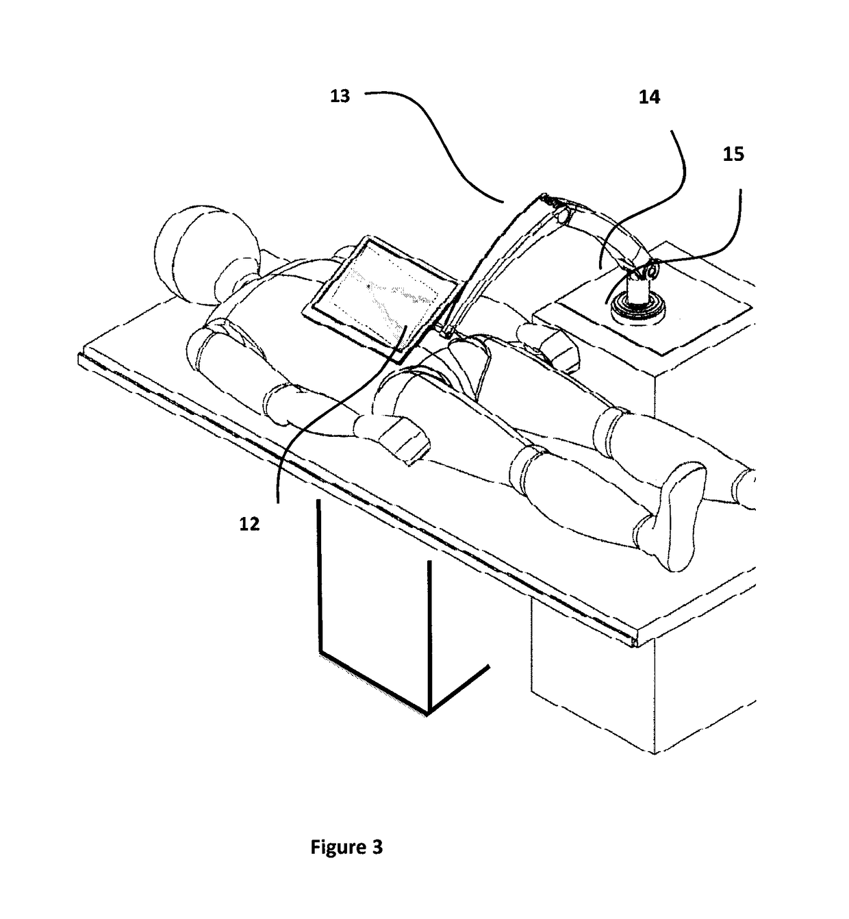
[0012]Embodiments of the invention possess inventive design elements that improve the ergonomics and increase the workspace of the virtual window surgical system. Furthermore, coupling the position and orientation of the display to the image allows the image to remain aligned to the patient for various positions and orientations of the display. To improve the workspace of the system, this invention allows for decoupling the relationship to reposition the display independently of the image. For instance, an aligned display may interfere with other equipment during some portion of the procedure and it may be desirable to un-align and reposition the display slightly to relieve the interference. Additionally this invention allows for a scaled coupling for improved ergonomics. For instance, moving the display with a unity ratio may cause the display to interfere with other equipment during some portion of the procedure or may make the screen difficult to view. A 1.5:1 scale would increase the ergonomics of the system while maintaining the visual coherency between the patient and the image. It should be noted that the display may be repositioned along multiple axes and in multiple directions and that the scaling may be different for different axes and directions. Additionally this invention provides a movable support structure to place a display directly in front of the physician, in between the physician and the patient. Ideally the images are presented in a fashion such that the images are substantially aligned with the patient. This invention details the methods and techniques needed to align the images to the patient. Many embodiments utilize a display that is mounted on a movable support structure that allows for the display to be positioned between the patient and the physician. The range of motion of the support structure and the degrees of freedom enable a wide range of display positions and orientations. In one embodiment, the patient is lying on a surgical table with the physician standing by the patient's side. The support structure allows the display to be brought over the patient. The physician can move and orient the display so the display is located roughly between him / her and the patient. This improves the ergonomics of the surgical workspace by allowing the physician's general gaze to remain in the same spot throughout the procedure, without having to look up to a display located away from the surgical site.
[0013]Furthermore, techniques are disclosed to track the position of the display, the imaging source, the patient, and the table. Tracking individual elements of the system allows the image to be aligned with the patient and constantly updated to accommodate for a moving patient, moving table, moving imaging source, or moving display.

Problems solved by technology

For instance, moving the display with a unity ratio may cause the display to interfere with other equipment during some portion of the procedure or may make the screen difficult to view.

Method used


Image

  • System and method for virtually tracking a surgical tool on a movable display
  • System and method for virtually tracking a surgical tool on a movable display
  • System and method for virtually tracking a surgical tool on a movable display

Examples


Embodiment Construction

[0080]While preferred embodiments of the present invention have been shown and described herein, it will be obvious to those skilled in the art that such embodiments are provided by way of example only. Numerous variations, changes, and substitutions will now occur to those skilled in the art without departing from the invention. It should be understood that various alternatives to the embodiments of the invention described herein may be employed in practicing the invention. It is intended that the following claims define the scope of the invention and that methods and structures within the scope of these claims and their equivalents be covered thereby.

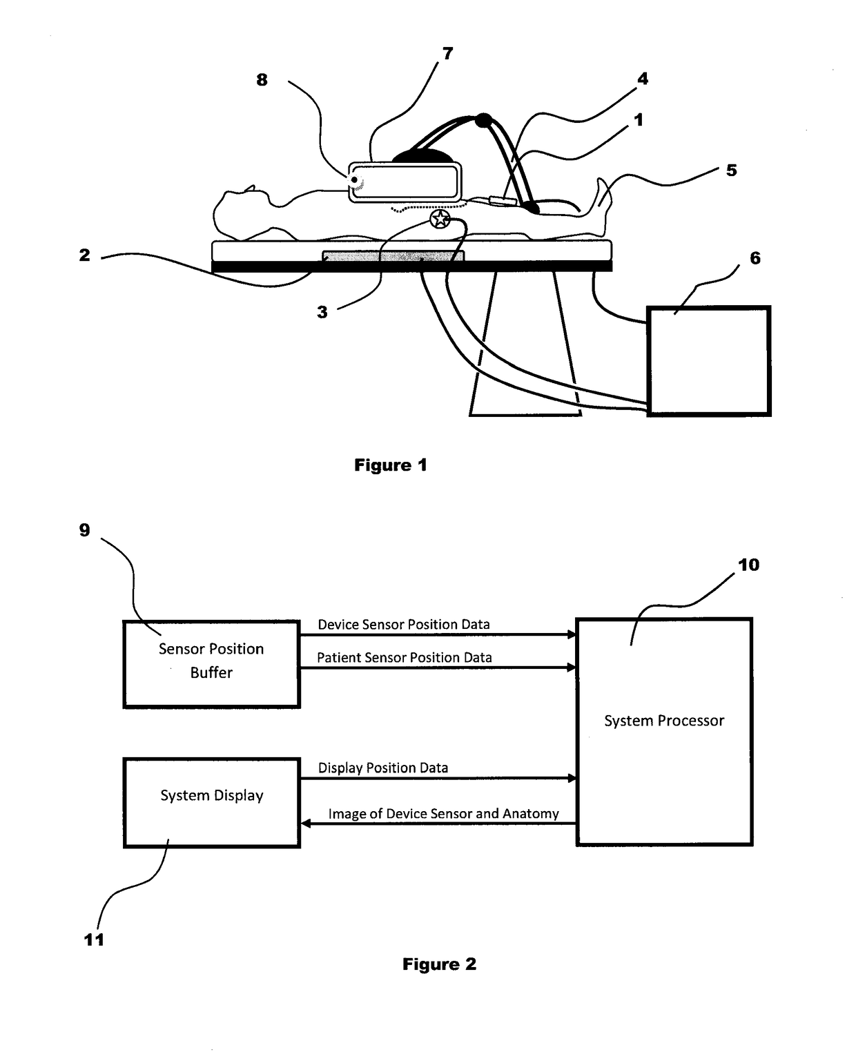
[0081]FIGS. 1-2 describe an embodiment for navigating a minimally invasive medical device within the patient using an acquired three-dimensional anatomical image shown in a display 7 that is substantially aligned to the patient anatomy. A sterile cover may be used to separate the display from the sterile operating field and the steril...


PUM


Abstract

The invention comprises a virtual window system that creates a visual coherency between the image of the patient and his or her anatomy and the patient by aligning the image of the patient anatomy on the display to the patient and presenting the image to the user that feels as if the user is looking directly into the patient through the display. The invention is designed to also display medical devices, such as a minimally invasive tool. The system substantially unifies the coordinate systems of the patient, the medical device, the display, and the physician's hands. The invention creates a visual coherency between the motion of the medical device in the image and the motion of the physician's hands manipulating the device. This invention also creates a visual coherency between the motion of the image in the display and of that display.

Description

CROSS-REFERENCE[0001]This application claims the benefit of U.S. Provisional Application No. 61 / 535,753, filed Sep. 16, 2011; U.S. Provisional Application No. 61 / 585,580 filed on Jan. 11, 2012; and U.S. Provisional Application No. 61 / 615,141 filed on Mar. 23, 2012, all of which are incorporated herein by reference in their entirety.BACKGROUND OF THE INVENTION1. Field of the Invention[0002]The invention relates generally to the diagnosis and treatment of disorders using minimally invasive techniques. In many minimally invasive procedures very small devices are manipulated within the patient's body under visualization from a live imaging source like ultrasound, fluoroscopy, or endoscopy. Live imaging in a minimally invasive procedure may be supplemented or replaced by displaying the position of a sensored medical device within a stored image of the patient anatomy.[0003]Many minimally invasive catheter procedures are conducted in expensive hospital settings by specialized physicians. ...

Claims


Application Information

Patent Timeline
Patent Type & Authority Patents(United States)
IPC IPC(8): A61B90/00A61B6/00A61B6/12A61B34/20A61B8/00A61B90/50
CPCA61B6/12A61B6/462A61B6/463A61B6/467A61B6/487A61B6/5235A61B6/547A61B34/20A61B90/50A61B6/4405F04C2270/041A61B8/00A61B2034/2051A61B2090/372A61B2090/504A61B2090/508A61B5/062A61B5/066A61B6/032A61B6/037A61B6/4417A61B6/4441A61B6/461A61B6/486A61B8/0841A61B8/4218A61B8/4245A61B8/4254A61B8/4263A61B8/4416A61B8/461A61B8/462A61B90/37A61B2034/2048A61B2034/2055A61B2034/2059A61B2090/365A61B2090/376A61B2090/3966
Inventor WALLACE, DANSTAHLER, GREGWAYDO, JAIMEGROGAN, AARON
Owner AURIS HEALTH INC
Learn More