Reluctance motor having inductor pole coils located between adjacent ones of the salient poles of a rotor

a technology of inductor pole coils and rotors, which is applied in the direction of synchronous motors, magnetic circuit rotating parts, magnetic circuit shapes/forms/construction, etc., can solve the problems of reducing the efficiency of induced current generation, etc., to achieve the effect of improving torque and high efficiency

Active Publication Date: 2018-03-13
SUZUKI MOTOR CORP
View PDF20 Cites 3 Cited by
  • Summary
  • Abstract
  • Description
  • Claims
  • Application Information

AI Technical Summary

Benefits of technology

[0013]Therefore, an object of the invention is to provide a reluctance motor which can collect loss energy to achieve the function of self-excitation and which can be rotated with high efficiency to thereby achieve improvement in torque.
[0020]Accordingly, it is not necessary to separately supply energy to the rotor-side electromagnet coils. Spatial harmonic components of the magnetic fluxes (which cause generation of iron loss) which cannot be used effectively in the background art can be collected to rotate the rotor with high efficiency. On this occasion, the same currents can be prevented from flowing into the inductor pole coils and the electromagnet coils and interfering with each other so that loss can be avoided. As a result, loss energy can be effectively collected to improve the torque of the reluctance motor.
[0021]According to the second aspect of the invention, the spatial harmonic components of the magnetic fluxes from the stator can be efficiently interlinked with the inductor pole coils which are located adjacently to the salient poles, i.e. on the outer circumferential surface side of the rotor, so that the spatial harmonic components of the magnetic fluxes can be efficiently collected to self-excite the inductor pole coils effectively to thereby supply large-capacity field currents to the electromagnet coils. Accordingly, a highly efficient self-excitation function can be constructed with a simple structure.
[0022]According to the third aspect of the invention, it is possible to prevent the magnetic fluxes generated around the inductor pole coils from interfering with each other so that it is possible to prevent self-excitation from being impeded. In addition, it is possible to prevent the existence of the inductor pole coils from being a factor causing reduction of the salient pole ratio. Accordingly, it is possible to achieve improvement in the torque generated due to the self-excitation effectively while avoiding reduction in reluctance torque.
[0023]According the fourth aspect of the invention, it is possible to increase the magnetic permeability inside the inductor pole coils so that it is possible to interlink magnetic fluxes of the spatial harmonic components from the stator with the inductor pole coils efficiently. Accordingly, it is possible to improve the collection rate of the loss energy. Thus, it is possible to improve the torque of the reluctance motor more effectively.
[0024]According to the fifth aspect of the invention, it is possible to optimize the ratio of the number P of salient poles of the rotor to the number S of slots of the stator so that the magnetic flux density can be distributed evenly to suppress electromagnetic vibration of the stator. Accordingly, it is possible to reduce energy loss caused by the electromagnetic vibration and it is possible to collect loss energy efficiently. Due to the reduction of the electromagnetic vibration, it is also possible to suppress electromagnetic noise.

Problems solved by technology

Each of the reluctance motors has a problem that it is difficult to obtain large torque when the reluctance motor is of a type using only reluctance torque, in comparison with a motor (electric motor) of a type which is driven by use of magnet torque generated by permanent magnets embedded on the rotor side.
Accordingly, magnetic interference takes place so that the induced currents cannot be generated efficiently but electromagnetic force generated thus is also weakened.
However, it has the same problem because induced currents cannot be generated efficiently in the same manner.
However, it is necessary to input excitation energy from the outside so that drive with high efficiency cannot be expected (lowering in the efficiency cannot be avoided).

Method used


Image

  • Reluctance motor having inductor pole coils located between adjacent ones of the salient poles of a rotor
  • Reluctance motor having inductor pole coils located between adjacent ones of the salient poles of a rotor
  • Reluctance motor having inductor pole coils located between adjacent ones of the salient poles of a rotor

Examples


Embodiment Construction

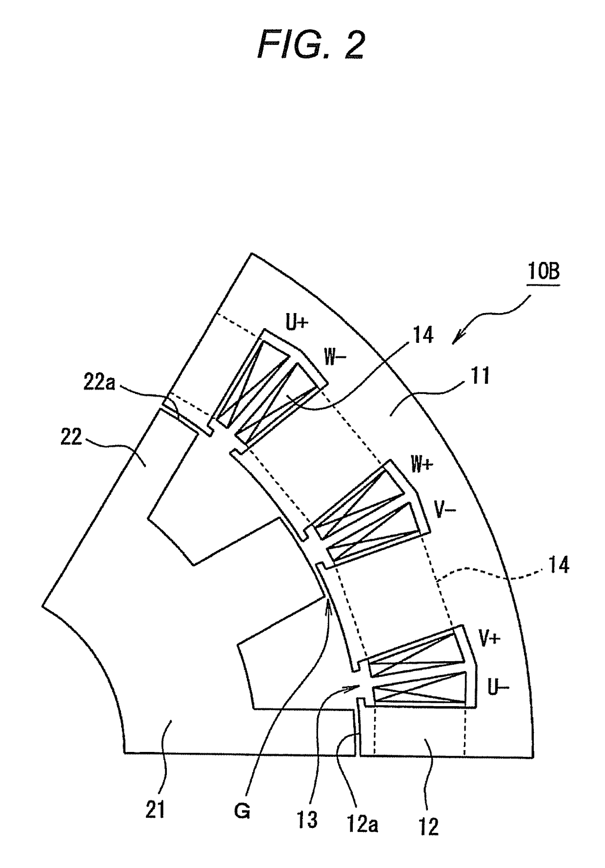
[0062]An embodiment of the invention will be described in detail below with reference to the drawings. FIGS. 1 to 21 are views for explaining an embodiment of a reluctance motor according to the invention. FIGS. 1 to 3 are radially sectional views of reluctance motors, each of which is depicted correspondingly to a mechanical angle of 60° around the axis thereof. The reluctance motor is manufactured to have a structure in which the depicted part corresponding to the mechanical angle of 60° is repeated periodically circumferentially.

[0063]In FIG. 1, a reluctance motor 10 starts at a reluctance motor 10B having a basic structure shown in FIG. 2 and uses a structure in which the problem inherent in a reluctance motor 10D shown in FIG. 3 and developed from the reluctance motor 10B can be solved. For example, the reluctance motor 10 has suitable performance when it is mounted as a drive source similar to an internal combustion engine on a vehicle or inside a wheel in a hybrid car or an e...


PUM


Abstract

A reluctance motor has: a stator provided with drive coils to which multiphase drive currents are inputted; and a rotor provided with a plurality of salient poles which receive primary rotating force when magnetic fluxes generated in the drive coils are interlinked with the rotor, and the rotor has: inductor pole coils which are placed on magnetic paths on which spatial harmonic components superimposed on the magnetic fluxes generated in the drive coils are interlinked with the rotor side so that induced currents can be generated in the inductor pole coils due to the spatial harmonic components of the magnetic fluxes; rectifier elements which rectify the induced currents generated in the inductor pole coils; and electromagnet coils as defined herein, and the inductor pole coils and the electromagnet coils do not serve for each other's purposes but are placed on the rotor individually.

Description

CROSS-REFERENCE TO RELATED APPLICATIONS[0001]This application claims the benefit of Japanese Application No. 2013-055860, filed Mar. 19, 2013, in the Japanese Patent Office. All disclosures of the document(s) named above are incorporated herein by reference.BACKGROUND OF THE INVENTION[0002]1. Field of the Invention[0003]The present invention relates to a reluctance motor. Particularly, it relates to a reluctance motor which has a self-excitation function so as to achieve highly efficient rotation.[0004]2. Description of the Related Art[0005]Reluctance motors are mounted as drive sources on various kinds of drive devices. Each of the reluctance motors has a problem that it is difficult to obtain large torque when the reluctance motor is of a type using only reluctance torque, in comparison with a motor (electric motor) of a type which is driven by use of magnet torque generated by permanent magnets embedded on the rotor side.[0006]Particularly, when a motor is mounted on a hybrid ele...

Claims


Application Information

Patent Timeline
Patent Type & Authority Patents(United States)
IPC IPC(8): H02K3/28H02K16/04H02K19/12H02K11/042H02K37/02H02K3/52H02K19/26H02K1/24H02K19/30H02K19/28H02K11/00H02K19/32
CPCH02K3/28H02K16/04H02K19/12H02K1/24H02K1/246H02K3/527H02K37/02H02K11/042H02K19/26H02K19/28H02K19/30H02K19/32H02K11/0094
Inventor AOYAMA, MASAHIRO
Owner SUZUKI MOTOR CORP
Why Eureka
Try Eureka