Rainscreen building siding

a technology for building siding and rainscreens, applied in building construction, covering/linings, construction, etc., can solve the problems of excessive material usage, extra step in the building process, and requiring separate materials and installation tim

Inactive Publication Date: 2018-03-13
HOOD ANDREW
View PDF24 Cites 10 Cited by
  • Summary
  • Abstract
  • Description
  • Claims
  • Application Information

AI Technical Summary

Benefits of technology

[0009]According to a first embodiment of the present invention there is disclosed a method for providing an integrated rainscreen with building siding on a vertical wall comprising providing at least one siding panel comprising an elongate planar member extending between first and second edges, top and bottom edges and having front and rear surfaces and at least one mounting block extending between first and second edges, top and bottom edges and having a rear surface wherein the at least one mounting block extends from the rear surface of the elongate planar member proximate to the top edge of the elongate planar member. The method further comprises aligning each of the at least one mounting block of the siding panel with a stud location in a vertical wall and fastening the siding panel to the studs in the vertical wall through the at least one mounting block with a plurality of fasteners, so as to create a rainscreen gap between the elongate planar member and the vertical wall.

Problems solved by technology

One disadvantage of using furring to create a rainscreen is that it is an extra step in the building process, requiring separate materials and installation time.
Another disadvantage is that the furring material is known to extend the full height of the building exterior which results in excessive material usage.
The excessive material use includes a requirement for a large quantity of nails, which attach both the furring and siding (through the furring) to a building, resulting in a large number of penetrations through the vapor barrier, and thus a greater risk of water or moisture absorption into the underlying wall.
This can delay construction and increase the overall building cost.

Method used


Image

  • Rainscreen building siding
  • Rainscreen building siding
  • Rainscreen building siding

Examples


Embodiment Construction

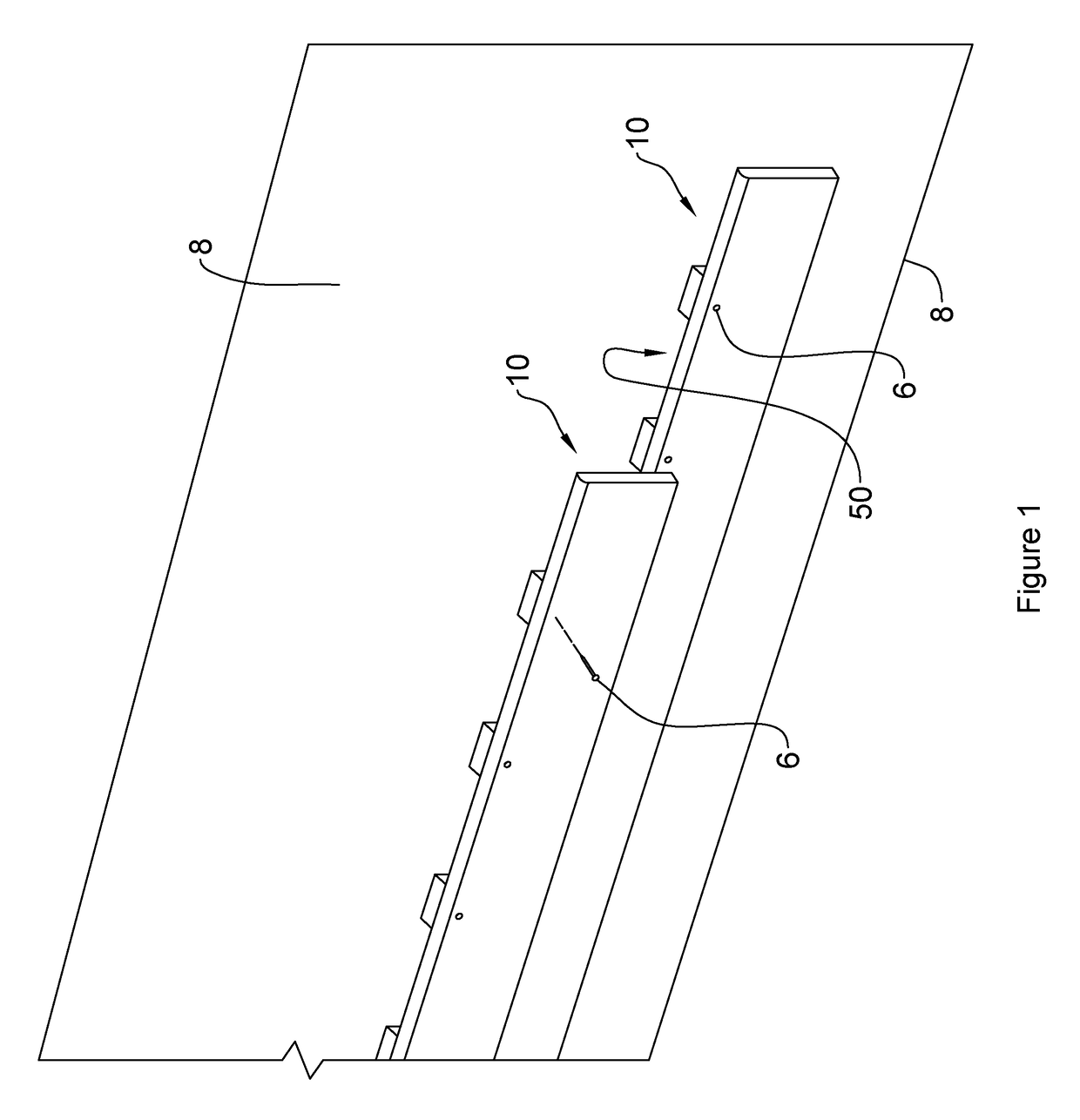
[0016]Referring to FIG. 1, a plurality of siding panels with an integrated rainscreen system according to a first embodiment of the invention are shown generally at 10. The siding panels 10 are mounted on an exterior wall 8 with a plurality of fasteners 6.

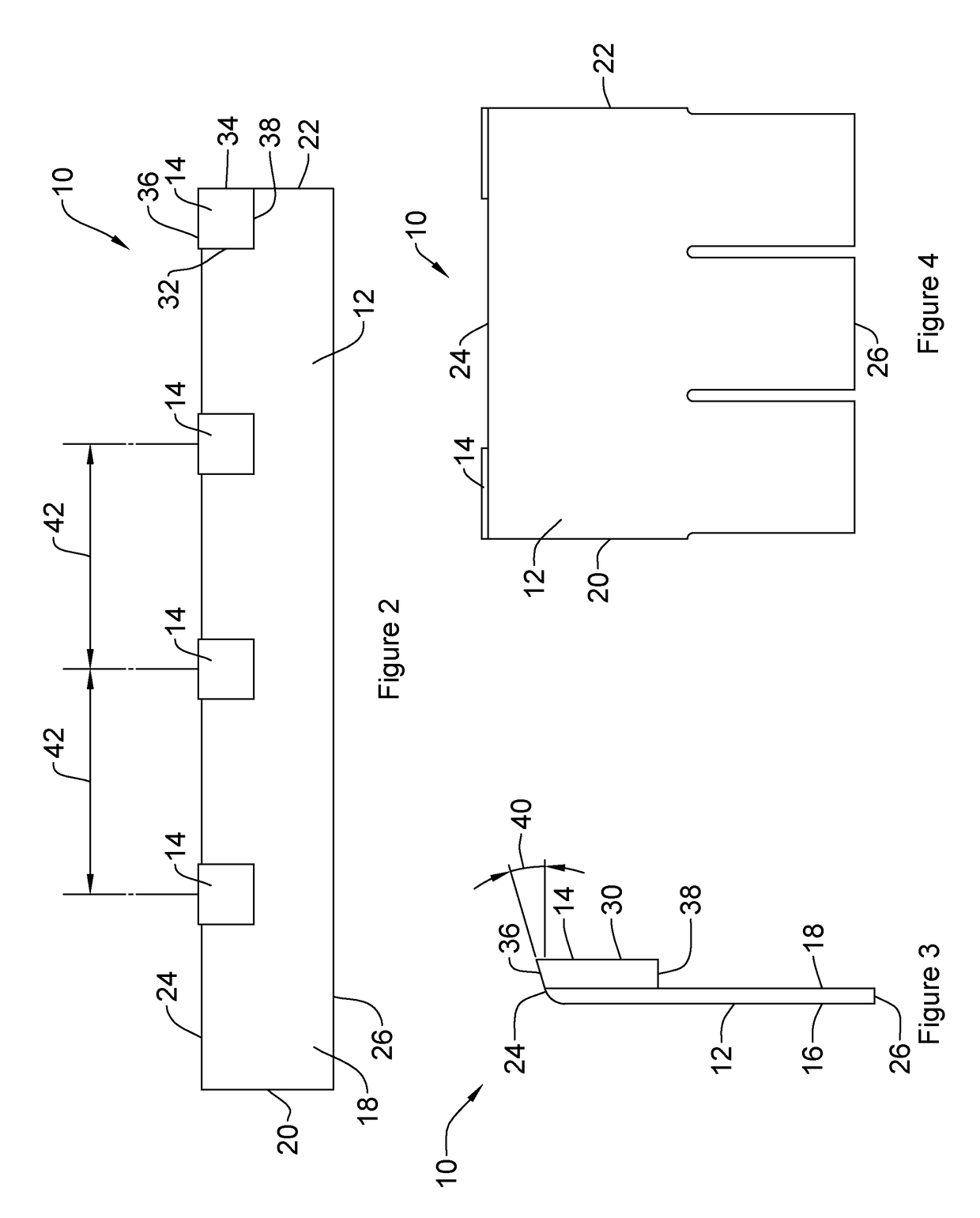
[0017]Each siding panel 10 comprises an elongate planar member 12 with a plurality of mounting blocks 14 thereon, as illustrated in FIGS. 2 and 3. The planar member 12, having front and rear surfaces, 16 and 18, respectively, extends between first and second edges, 20 and 22, respectively, and between top and bottom edges, 24 and 26, respectively. The planar member 12 may be substantially rectangular in shape, as illustrated in FIG. 2, although it will be appreciated that aesthetic edging details may be included, as well, such as illustrated in FIG. 4 with a plurality of decorative notches, by non-limiting example. The planar member 12 may be formed of any desired rigid material, such as, by way of non-limiting example, wood, cemen...


PUM


Abstract

An apparatus and method for siding a building wherein the apparatus comprises an elongate planar member extending between first and second edges, top and bottom edges and having front and rear surfaces and at least one mounting block extending between first and second edges, top and bottom edges and having a rear surface wherein the at least one mounting block extends from the rear surface of the elongate planar member proximate to the top edge of the elongate planar member. The method comprises aligning each of the at least one mounting block of the siding panel with a stud location in a vertical wall and fastening the siding panel to the studs in the vertical wall through the at least one mounting block with a plurality of fasteners, so as to create a rainscreen gap between the elongate planar member and the vertical wall.

Description

BACKGROUND OF THE INVENTION1. Field of Invention[0001]The present invention relates generally to building materials, and in particular to building siding providing an integrated rainscreen.2. Description of Related Art[0002]Exterior walls of both residential and commercial buildings are typically constructed in layers. The inside layers of the walls support the floors, interior walls and roof, while the outside layers protect the inside of the building from the outdoors. Many buildings utilize building siding on the exterior walls to both protect the building from the weather as well as provide an aesthetic covering.[0003]Building siding may be formed of horizontal or vertical boards, shingles or sheet materials, and may be formed using a variety of materials. To improve the ability of the siding to keep the walls dry, rainscreen construction methods are required by many current building codes. With a rainscreen, an air gap is formed between the outer siding and the moisture barrier...

Claims


Application Information

Patent Timeline
Patent Type & Authority Patents(United States)
IPC IPC(8): E04F13/08E04F13/18E04F13/14E04F13/10
CPCE04F13/0864E04F13/10E04F13/14E04F13/18E04F13/007
Inventor HOOD, ANDREW
Owner HOOD ANDREW
Why Eureka
Try Eureka