Switching apparatus and method for varying an impedance of a phase line of a segment of an electrical power line

a technology of electrical power line and phase line, which is applied in the direction of air-break switch, high-tension/heavy-dress switch, and reactive power adjustment/elimination/compensation, etc., which can solve the problem of not allowing for efficient and safe switching of the conductors of the segment of the electric power lin

Active Publication Date: 2018-03-06
HYDRO QUEBEC CORP
View PDF12 Cites 2 Cited by
  • Summary
  • Abstract
  • Description
  • Claims
  • Application Information

AI Technical Summary

Problems solved by technology

One of the drawbacks which can be found in at least some of the above-mentioned switching apparatuses and methods is that some of these apparatuses and methods may not allow for an efficient and safe switching of the conductors of a segment of an electric power line.

Method used


Image

  • Switching apparatus and method for varying an impedance of a phase line of a segment of an electrical power line
  • Switching apparatus and method for varying an impedance of a phase line of a segment of an electrical power line
  • Switching apparatus and method for varying an impedance of a phase line of a segment of an electrical power line

Examples


Embodiment Construction

[0037]The present invention relates to a switching apparatus and corresponding method for varying an impedance of a phase line of a segment of an electrical power line.

[0038]Some potential applications of the present invention include the following: line impedance modulator (LIM); line deicer; on-line power supply; current limiter; sub-synchronism resonance damping; inter-area oscillations damping; and breaking resistor.

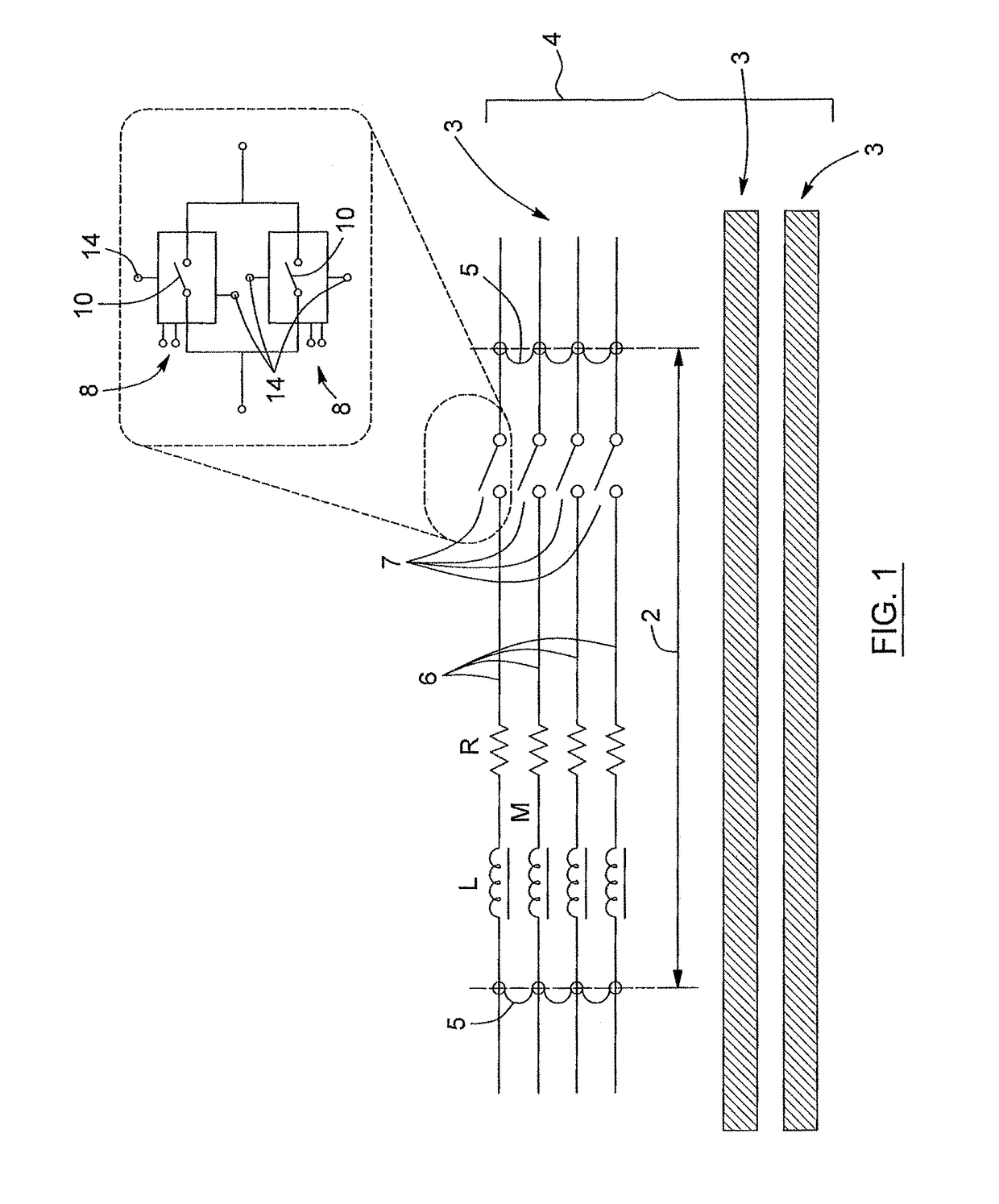
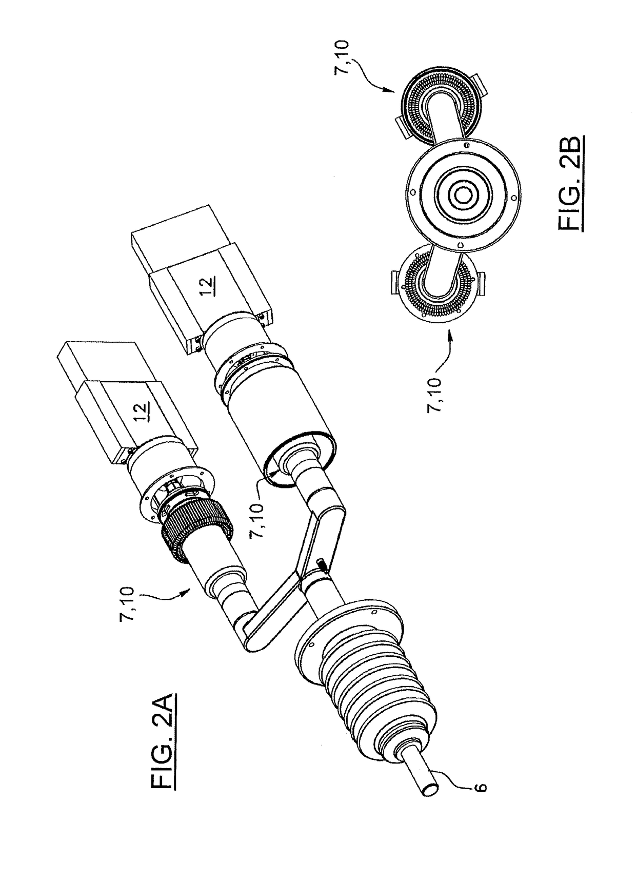
[0039]Referring to FIGS. 1 to 11, the switching apparatus is shown acting on a phase line 3 of a segment 2 of an electrical power line 4. The phase line 3 includes “n” number of conductors 6, where n is greater than or equal to two. In the example provided in FIG. 1, the phase line 3 is shown as having four conductors 6, but the phase line 3 can also have more or fewer conductors 6 if required. Similarly, there can be more or fewer than the three phase lines 3 shown in FIG. 1. The n conductors 6 are electrically insulated from each other and short-circuited together ...


PUM


Abstract

The switching apparatus and the method are for varying the impedance of a phase line of a segment of an electrical power line. The phase line includes n conductors electrically insulated from each other and short-circuited together at two ends of the segment. The apparatus comprises a controllable interrupter connected in series for each conductor; a parameter detector; a first controller for controlling the interrupters; and a disabling unit for disabling the interrupters. The disabling unit comprises n controllable switches associated with the interrupters, position detectors for detecting which of the interrupters is closed, and a second controller having a command output to command the controllable switches and ensure that, at all operating times, at least one of the interrupters is closed and disabled.

Description

FIELD OF THE INVENTION[0001]The present invention relates to a switching apparatus and a method for varying an impedance of a phase line of a segment of an electrical power line.BACKGROUND OF THE INVENTION[0002]Known in the art is U.S. Pat. No. 7,639,460 B2. This document describes a switching apparatus and a method for varying the impedance of a phase line of a segment of an electrical power line. The phase line includes n conductors electrically insulated from each other and short-circuited together at two ends of the segment. More particularly, the apparatus includes at least one first vacuum interrupter connected in series with at least one of the conductors, at least one first controllable motor for selectively opening and closing the at least one first vacuum interrupter, and a controller for controlling the at least one first controllable motor according to a parameter representative of the current operating conditions of the phase line. U.S. Pat. No. 7,639,460 B2 is herein i...

Claims


Application Information

Patent Timeline
Patent Type & Authority Patents(United States)
IPC IPC(8): H01H33/28H01H33/66H01H33/52H01H33/02H01H31/34H02J3/18H01H33/59H01H33/36
CPCH01H33/59H01H33/66H01H33/52H02J3/18H01H31/34H01H33/027H01H33/28H01H33/36Y02E40/30
Inventor COUTURE, PIERRE
Owner HYDRO QUEBEC CORP
Why Eureka
Try Eureka