
Virtualization method for an access network system and its management architecture

a virtualization method and access network technology, applied in hybrid switching systems, instruments, program control, etc., can solve problems such as severe service disruption and significant disadvantage for operators

Inactive Publication Date: 2018-02-27
OLIVER SOLUTIONS
View PDF8 Cites 4 Cited by
  • Summary
  • Abstract
  • Description
  • Claims
  • Application Information

AI Technical Summary

Benefits of technology

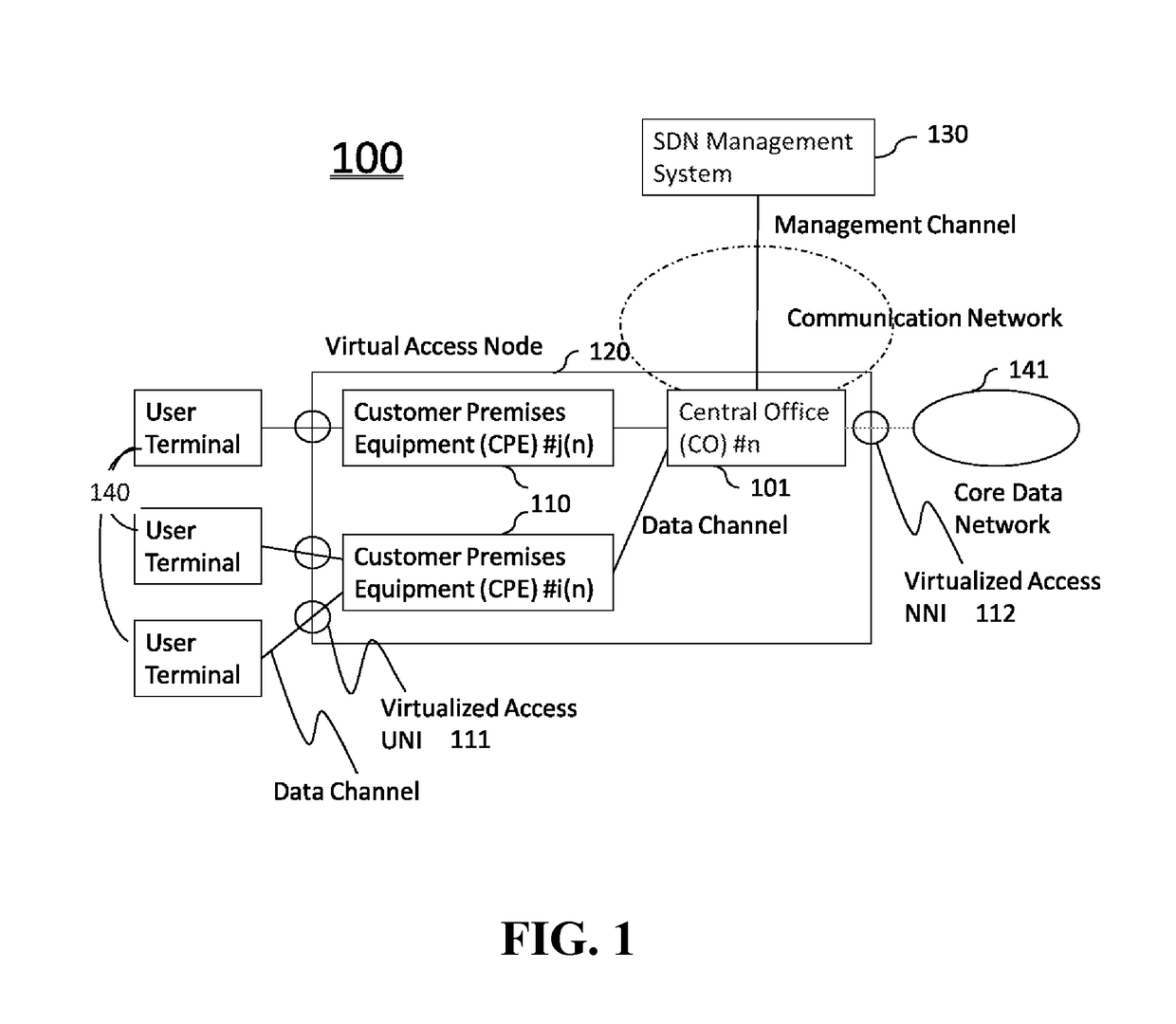
The present invention relates to a telecommunication network system that supports a SDN-based virtual access node which can be controlled by a SDN Management System as a single device. The virtual access node provides interface points between user terminals and a core data network through more than one virtualized access UNI and a virtualized access Network Node Interface. The SDN Management System can control the virtual access node without needing information about its internal structure. The invention also includes a control mechanism for flow forwarding configuration inside the virtual access node. This invention further supports a multi-device structure and provides a more flexible and efficient management of telecommunication networks.

Problems solved by technology

Although applying an integrated SDN management across the network including the access node can maximize the benefit in the CPAEX and the OPEX, network operators have deployed the legacy access nodes in large and then it becomes a significant disadvantage for operators who want to use OpenFlow because each of the standalone device must be a standalone SDN native device.
This situation will enforce operators to replace the whole legacy access nodes if they plan to manage them under integrated SDN management, especially the replacement of the whole CPE in the customer premises will cause a severe service disruption.

Method used


Image

  • Virtualization method for an access network system and its management architecture
  • Virtualization method for an access network system and its management architecture
  • Virtualization method for an access network system and its management architecture

Examples


Embodiment Construction

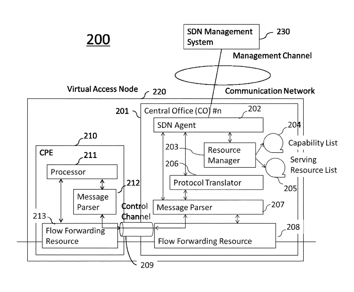
[0019]In FIG. 1, a virtual access node 120 comprises a CO 101 and more than one CPE 110. The CO 101 of the virtual access node 120 communicates with a SDN Management System 130 through a management channel in a communication network. The SDN Management System 130 controls the virtual access node 120 as a single network node and the SDN Management System 130 understands more than one virtualized access UNI 111 and a virtualized access NNI 112 as the interface points of the virtualized access node 120 to interconnect with corresponding user terminals 140 and a core data network 141 for forwarding and receiving user data flows both in the downstream and the upstream directions. The SDN Management System 130 controls multiple virtual access nodes through the communication network.

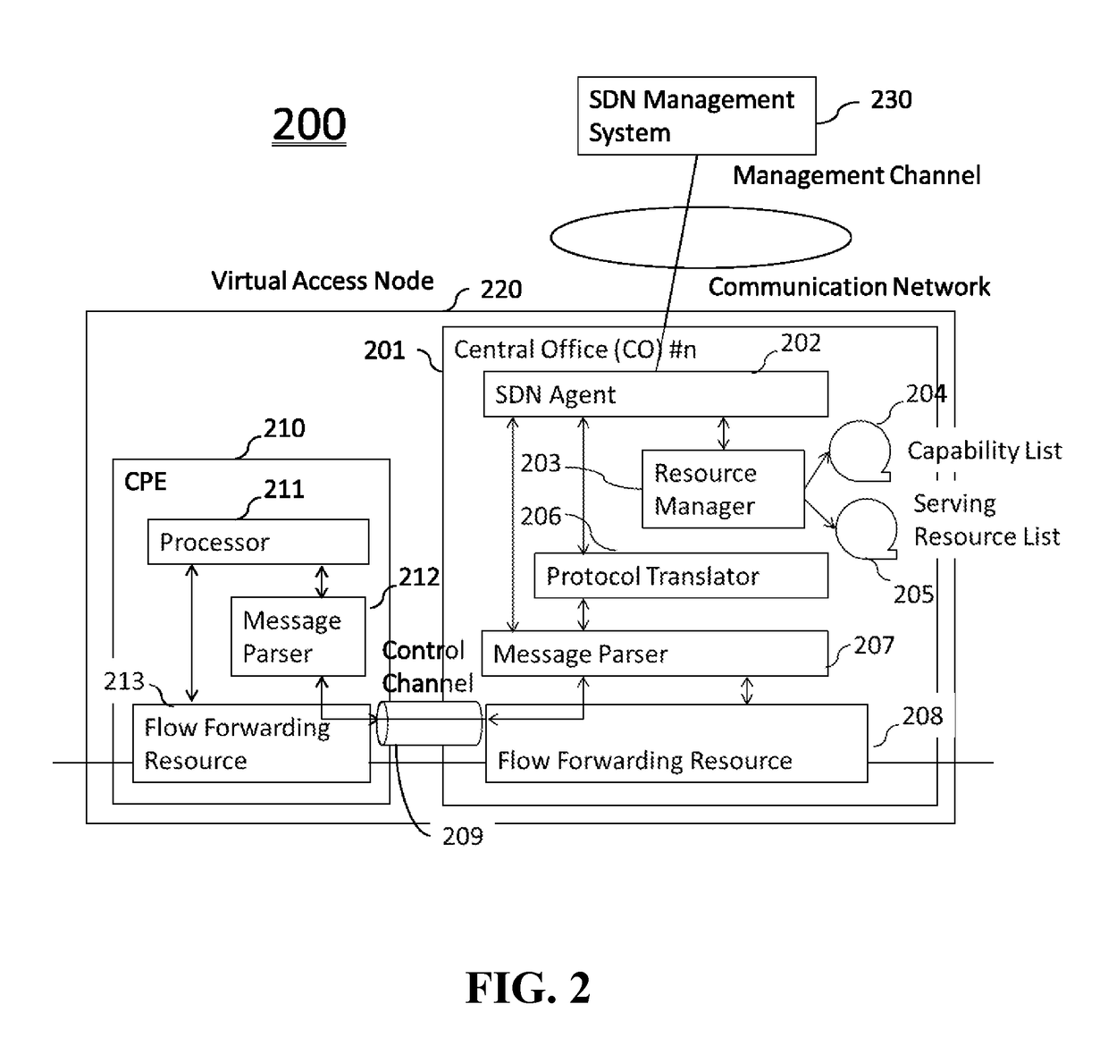
[0020]FIG. 2 describes function blocks in the virtual access node 220 of the current patent. A SDN Agent 202 resides inside of the CO 201 interacts with the SDN Management System 230 to send and receive SDN con...


PUM


Abstract

A virtual access node comprising of a Central Office (CO) and more than one Customer Premises Equipment (CPE), that can be a mixture of a SDN native and a SDN non-native device, supports a virtualized access Network Node Interface (NNI) in the CO and a virtualized access User Network Interface (UNI) in the CPE. A Software Defined Network (SDN) Management System using a SDN control message configures an user data flow in the virtual access node by designating a virtualized access NNI, a virtualized access UNI, and flow forwarding configuration parameters without specifying exact flow forwarding resources. The virtual access node allocates and configures a set of required flow forwarding resources which are distributed in the CO and / or the CPE by that device oriented partitioned control messages with translating in the legacy control message when the resource is in a SDN non-native device.

Description

CROSS REFERENCE TO RELATED APPLICATIONS[0001]This application claims priority benefit of U.S. Provisional Application No. 62 / 032,578, filed on Aug. 3, 2014 by inventor Toshihiko KusanoFIELD OF THE INVENTION[0002]The present invention relates to a network virtualization for a telecommunication network node comprises of SDN non-native devices to manage them seamlessly among with SDN native devices from a SDN Management System.[0003]The present invention is particularity suitable for an access node comprises a Central Office (CO) and more than one Customer Premises Equipment (CPE).BACKGROUND OF THE INVENTION[0004]Recently, Software Defined Network (SDN) has been widely recognized as the next generation network management scheme in the packetized data communication era. Current SDN defines SDN native control message and protocol, OpenFlow is the well-known standard for the control message, but it may not be true to determine the protocol is the only choice applicable to the SDN concept....

Claims


Application Information

Patent Timeline
Patent Type & Authority Patents(United States)
IPC IPC(8): H04L12/64G06F9/455
CPCH04L12/6418G06F2009/45595
Inventor KUSANO, TOSHIHIKO
Owner OLIVER SOLUTIONS
Learn More